Top Posts
Deploying & Configuring the VMware LCM Bundle Utility...
VMware Cloud Foundation: Don’t Forget About SSO Service...
VMware Explore Las Vegas 2025: Illuminating the Path...
Securing Software Updates for VMware Cloud Foundation: What...
VMware Cloud Foundation 5.2: A Guide to Simplified...
VMware Cloud Foundation 5.2: Unlocking Secure Hybrid Cloud...
VMware Cloud Foundation – Memory Tiering: Optimizing Memory...
Decoding VMware Cloud Foundation: Unveiling the numerous amount...
VMware Cloud Director 10.6.1: Taking Cloud Management to...
Omnissa Horizon Upgrade 2406 to 2412
Virtual Bytes
  • Home
  • Home Data Center 2025
  • VMware
    • Cloud
    • Datacenter & Cloud Infrastructure
      • VMware ESXi
      • VMware vCenter
      • VMware vSAN
    • Networking & Security
    • Desktop & App Virtualization
      • Omnissa Horizon
    • Troubleshooting
    • Ansible
  • Education
  • Hardware
    • Hardware Tips & Tricks
  • Events
  • About
    • About Me
    • Home Lab Archives
      • Home Lab 2020-2022
      • Home Lab 2016-2020
Category:

Networking

NetworkingVMware vSAN

VMware vSAN and Remote Direct Memory Access

by Tommy Grot January 5, 2024
written by Tommy Grot 3 minutes read

Welcome to the first blog post of 2024! We are thrilled to kick off the year with a topic that is bound to ignite your vSAN Cluster. Get ready to dive into the world of RDMA (Remote Direct Memory Access) and vSAN (Virtual Storage Area Network) implementation. These cutting-edge technologies are revolutionizing the way data is transferred and stored, promising lightning-fast speeds and unparalleled efficiency. Whether you are a tech enthusiast, a system administrator, or simply someone intrigued by the latest advancements in the tech universe, this blog post will unravel the mysteries of RDMA and vSAN, leaving you with a newfound understanding and enthusiasm for these game-changing innovations. So, buckle up and lets get ready!

Lets configured your ESXi Host to be ready for RDMA for vSAN

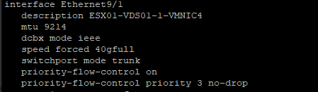
First thing you will want your Core Networking Switches to have Data Center bridging configured for all interfaces that are connected to your vSAN Cluster. Link to Arista

Example Syntax From my Arista DCS-7050QX-32S-F
   description ESX01-VDS01-1-VMNIC4
   mtu 9214
   dcbx mode ieee
   speed forced 40gfull
   switchport mode trunk
   priority-flow-control on
   priority-flow-control priority 3 no-drop

Sample Config

So, now that the networking is prepared next we will need to SSH into each ESXi Host and you will need configure the settings below:

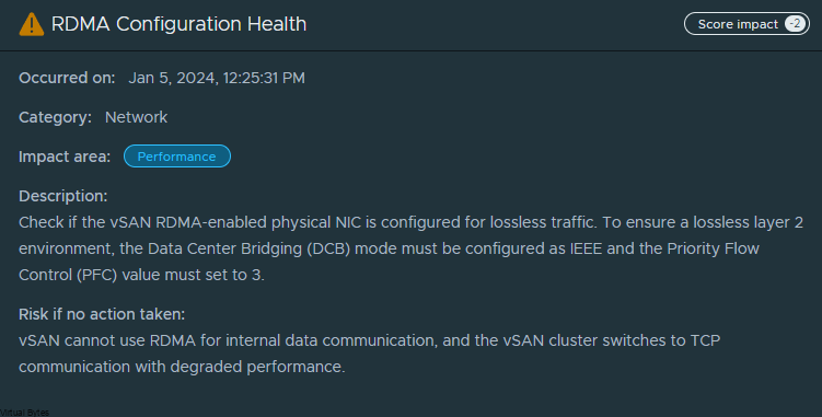
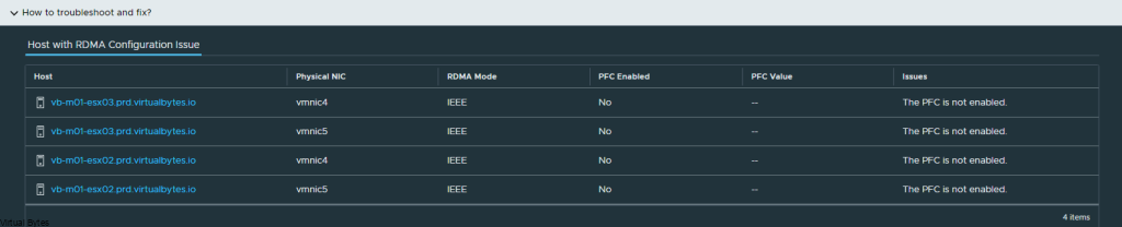
Example of vSAN Cluster Health regarding RDMA not configured

While in SSH – you will need to configured each host with the parameters’ below in each code block

dcbx int Set DCBX operational mode
Values : 0 – Disabled, 1 – Enabled Hardware Mode, 2 – Enabled Software Mode, 3 – If Hardware Mode is supported Enable Hardware Mode, else Enable Software

esxcli system module parameters set -m nmlx5_core -p dcbx=3

pfctx int 0x08 Priority based Flow Control policy on TX.
Values : 0-255
It’s 8 bits bit mask, each bit indicates priority [0-7]. Bit value:
1 – generate pause frames according to the RX buffer threshold on the specified priority.
0 – never generate pause frames on the specified priority.
Notes: Must be equal to pfcrx.
Default: 0

pfcrx int 0x08 Priority based Flow Control policy on RX.
Values : 0-255
It’s 8 bits bit mask, each bit indicates priority [0-7]. Bit value:
1 – respect incoming pause frames on the specified priority.
0 – ignore incoming pause frames on the specified priority.
Notes: Must be equal to pfctx.
Default: 0

trust_state int Port policy to calculate the switch priority and packet color based on incoming packet
Values : 1 – TRUST_PCP, 2 – TRUST_DSCP
Default: 1

esxcli system module parameters set -m nmlx5_core -p "pfctx=0x08 pfcrx=0x08 trust_state=2 max_vfs=0"

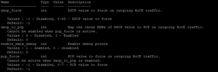
pcp_force int PCP value to force on outgoing RoCE traffic.
Cannot be active when dscp_to_pcp is enabled.
Values : -1 – Disabled, 0-7 – PCP value to force
Default: -1

dscp_force int DSCP value to force on outgoing RoCE traffic.

Values : -1 – Disabled, 0-63 – DSCP value to force
Default: -1

esxcli system module parameters set -m nmlx5_rdma -p "pcp_force=-1 dscp_force=26"

Now, that your have configured all the ESXi hosts, you will need to repeat the syntax above to each host you have. Once updated you will need to put each host in maintenance mode and reboot each host.

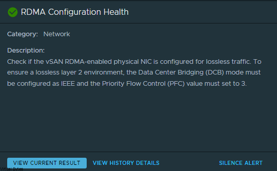
Once all ESXi hosts are configured and rebooted, vSAN Health should report back RDMA Configuration Healthy.

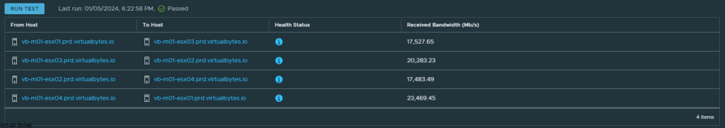
Below are some Network Backbone tests over RDMA!

January 5, 2024 2 comments 1.8K views
1 FacebookTwitterLinkedinEmail
CloudNetworkingVMware NSX

Deploying VMware NSX Advanced Load Balancer

by Tommy Grot May 3, 2023
written by Tommy Grot 2 minutes read

Today’s topic is on VMware NSX Advanced Load Balancer (AVI). We will walk through the steps of deploying a NSX ALB overlayed on top of your NSX Environment.

Features

  • Multi-Cloud Consistency – Simplify administration with centralized policies and operational consistency
  • Pervasive Analytics – Gain unprecedented insights with application performance monitoring and security
  • Full Lifecycle Automation – Free teams from manual tasks with application delivery automation
  • Future Proof – Extend application services seamlessly to cloud-native and containerized applications

More information at VMware’s site here

What You Will Need:

  • A Configured and running NSX Environment
  • NSX ALB Controller OVA (controller-22.1.3-9096.ova)
  • Supported Avi controller versions: 20.1.7, 21.1.2 or later versions
  • Obtain IP addresses needed to install an appliance:
    • Virtual IP of NSX Advanced Load Balancer appliance cluster
    • Management IP address
    • Management gateway IP address
    • DNS server IP address
  • Cluster VIP and all controllers management network must be in same subnet.

Lets start with deploying controller OVF

I like to keep neat and consistent names the following names I utilized:

Virtual Machine Names:
  • nsx-alb-01
  • nsx-alb-02
  • nsx-alb-03

You need total of 3 Controllers deployed to create a High Available NSX ALB.

Click the Ignore All, or you will get this error as show below

Select your datastore ->

Click Next ->

My DNS Records:

  • nsx-alb-01.virtualbytes.io
  • nsx-alb-02.virtualbytes.io
  • nsx-alb-03.virtualbytes.io

We are deploying!

Access your first appliance via its FQDN that you have set in the steps above.

Create your password for local admin account

Create your passphrase, and your DNS resolvers, and DNS Search Domains.

Skip SMTP if not needed, but if you need a mail server please fill out your required SMTP IP and Port

  • Service Engines are managed within the tenant context, not shared across tenants to enable the Tenant Context Mode.
  • Service Engines are managed within the provider context, shared across tenants to enable the Provider Context Mode.

That is it for the initial deployment, next we will add our other 2 additional NSX ALB nodes for HA setup.

Go to Administration -> Controller -> Nodes

Click Edit ->

For your 2 additional NSX ALB nodes you will need to provide an IP Address and hostname and password.

Sample of what it should look like for all 3 ALB appliances

A simple topology of what we have deployed.

That is it! from now on you can configure for what use case you will NSX-ALB for. A next blog post will go through how to step up a NSX-T Cloud.

Licensing Flavors – If you click on the little cog icon next to the Licensing. You will see different tiers.

Different License Tiers that are apart of NSX-ALB Licensing model.

May 3, 2023 0 comments 2.6K views
0 FacebookTwitterLinkedinEmail
CloudNetworking

Reverse Proxy & Load Balancing a Web Server with VMware NSX Advanced Load Balancer

by Tommy Grot December 16, 2022
written by Tommy Grot 3 minutes read

Want to setup a load balancer and reverse proxy with VMware NSX Advanced Load Balancer, and you want to replace your Nginx Reverse Proxy, well let’s get started!

First, we will make sure that you already have NSX ALB setup and configured within your environment, this walkthrough will only step you through on building a Virtual Service and Pools and VIPs for your multiple web servers. During this deployment you can set up many different FQDNs.

Requirements

  • Public FQDN
  • Lets Encrypt SSL Certificate (Wild Card or SAN or Single Cert)
  • NAT – Service Engine
  • Virtual IP
  • Service Pool
  • Web Server(s)

Product Versions:

  • VMware NSX ALB: 22.1.2
  • VMware NSX: 4.0.1.1.0.20598726

Steps

Login as an administrator account to NSX ALB ->

Go to Virtual Services -> Create Virtual Service

Select -> Advanced Setup

Next prompt -> Select your Cloud (For my setup I am doing everything NSX Overlay Backed)

Click Next -> Select your VRF Context (I am using a Tier 1 Gateway)

So now at this point – you should see this screen below, we will create a New Virtual Service, this will be the main ingress and egress point of your network and the external world. I have a NAT from my firewall going to this Virtual Service (VIP) Virtual IP.

  • Name: External-ParentSNI-VS (This is my naming convention, but you can choose your own)
  • Select: Enable Virtual Hosting VS
  • Virtual Hosting Type: SNI
  • VS VIP – (Create the main VIP for Ingress/Egress NAT, that is routable)
  • Application Profile: System-Secure-HTTP
  • WAF ( You can enable if you would like too, this is optional)
  • Service Port ( 80,443 – For 443 you will want to select SSL)
  • Pool – (Create a Pool, I used one of my very first web servers to start the pool)
  • SSL Certificate – Select your Cert – by default ALB will put System-Default-Cert

Click Save / Next – For this portion of the Virtual Service with Parent SNI we are done, next we will deploy the Child SNI which will be a parent to the main Ingress/Egress SNI Virtual Service.

As an example – I will use my Virtual Bytes SNI Child Virtual hosting.

Click on drop down for Pool, if you have not created a pool we will do so now.

  • Name: External-Parent-SNI-VS-Pool
  • VRF Context – Your Tier 1 Gateway
  • Default Server Port: 443

Select your first webserver, this will let you start the Virtual Service. You can do it via a IP Group or IP Address or DNS Name as well as have the capability to use a security group from NSX.

After you have created all the required services you should be able to access your web server from an internal or external (Internet) if you have NAT’d. But for the next steps we will repeat the steps for a Child SNI.

Child SNI Setup

  • Go to Virtual Services – > Click on Create Virtual Service (Advanced)
  • Name: You Web Server
  • Check – Virtual Hosting VS
  • Virtual Hosting Type: SNI
  • Virtual Hosting Parent: External-ParentSNI-VS (or your own naming)
  • Domain Name: www.yourdomain.com
  • Application Mode: System Secure-HTTP
  • Pool: Create a pool for the Virtual Machine or service you want to load balance
  • SSL Certificate: Select your Certificate

Click Next all the way till the end, and now you have successfully setup a Child SNI which now you can replicate the same steps for multiple web servers, and you no longer need to NAT anymore IPs, since your main ingress/egress is already NAT’d and everything will flow through the main Parent service.

December 16, 2022 0 comments 3.1K views
1 FacebookTwitterLinkedinEmail
CloudNetworking

Workspace One Access Integration with NSX-T

by Tommy Grot May 29, 2022
written by Tommy Grot 1 minutes read

Tonight’s quick walkthrough on how to integrate NSX-T and Workspace One Access (VIDM) This allows workspace one to create a OAuth connection with NSX-T where you can control user access via WSOA and leverage Active directory and instead of trying to manage local accounts and dealing with a mess!

Login into NSX-T Manager -> System

User Managment -> Edit

Then Login into Workspace One Access ->Catalog ->Settings

Go to Remote App Access -> Click on Create Client

Fill in the Name of the Client ID, I chose nsx-mgr-OAuth-wsoa

Generate Shared Secret, copy it so then when we go back to Workspace One Access we can paste it in.

Now. that we are back in NSX-T, fill in your FQDN for your workspace one appliance if you have a load balancer setup then enable it but for this walk through we are doing a single Workspace One Appliance.

Now, that we have the few things filled out, Dont click Save Just yet!

SSH into your Workspace One Appliance. We will get the SSL Thumbprint.

Change directory to /usr/local/horizon/conf

If you are using a CA Signed Certificate you will need to follow the prompt below.

openssl s_client -servername workspace.yourfqdn.io -connect workspace.yourfqdn.io:443 | openssl x509 -fingerprint -sha256 -noout

There is our fingerprint! Now we copy and go back to NSX-T

After the Integration is complete, now go back to Workspace One and add the users / groups through Active Directory.

May 29, 2022 0 comments 2.4K views
0 FacebookTwitterLinkedinEmail
EducationNetworking

VMware NSX Ninja Program

by Tommy Grot May 13, 2022
written by Tommy Grot 1 minutes read

So where to begin? My goal I have is to become a VCIX within DCV and NV, but it will come soon! I have been passionate about learning and progressing my skill sets within VMware Solutions and creating complex environments, but with coming along with few folks at VMware which invited me into VMware NSX Ninja Program for NSX-T and VCF Architecture. As this Program is geared toward the Intermediate / Expert level it does challenge you but I have managed to succeed! I have finished Week 1 of 3, the VMware Certified Instructors are amazing they teach and walk-through real-world solutions which let you get a good understanding of the many bells and whistles that NSX-T and VCF can offer! As i go through the journey of the NSX Ninja, I will be adding more great content to this post! Stay Tuned 🙂

NSX Ninja Week 1 – Overview

May 13, 2022 0 comments 1.5K views
1 FacebookTwitterLinkedinEmail
NetworkingVMware NSX

NSX-T 3.2 VRF Lite – Overview & Configuration

by Tommy Grot February 20, 2022
written by Tommy Grot 7 minutes read

Hello! Today’s blog post will be about doing a NSX-T Tier-0- VRF Tier-0 with VRF Lite Toplogy and how it will be setup! We will be doing a Active / Active Toplogy with VRF.

A little about what a VRF is – (Virtual Routing and Forwarding) this allows you to logically carve out a logical router into multiple routers, this allows you to have multiple identical networks but logically segmented off into their own routing instances. Each VRF has its own independent routing tables. this allows to have multiple networks be segmented away from each other and not overlap and still function!

Benefit of NSX-T VRF Lite – allows you to have multple virtual networks on on a same Tier-0 without needing to build a seperate nsx edge node and consuming more resources to just have the ability to segment and isolate a routing instance from another one.

Image from VMware

What is : Transport Zone (TZ) defines span of logical networks over the physical infrastructure. Types of Transport Zones – Overlay or VLAN

When a NSX-T Tier-0 VRF is attached to parent Tier-0, there are multiple parameters that will be inherited by design and cannot be changed:

  • Edge Cluster
  • High Availability mode (Active/Active – Active/Standby)
  • BGP Local AS Number
  • Internal Transit Subnet
  • Tier-0, Tier-1 Transit Subnet.

All other configuration parameters can be independently managed on the Tier-0:

  • External Interface IP addresses
  • BGP neighbors
  • Prefix list, route-map, Redistribution
  • Firewall rules
  • NAT rules

First things first – login into NSX-T Manager, once you are logged in you will have to prepare the network and tranport zones for this VRF lite topology to properly work, as it resides within the overlay network within NSX-T!

Go to Tier-0 Gateways -> Select one of your Tier-0 Routers that you have configured during initial setup. I will be using my two Tier-0’s, ec-edge-01-Tier0-gw and ec-edge-02-Tier0-gw for this tutorial along with a new Tier-0 VRF which will be attached to the second Tier-0 gateway.

So, first thing we will need to prepare two (2) segments for our VRF T0’s to ride the overlay network.

Go to – Segments -> Add a Segment, the two segments will ride the overlay transport zone, no vlan and no gateway attached. Add the segments and click on No for configuring the segment. Repeat for Second segment.

Below is the new segment that will be used for the Transit for the VRF Tier-0.

Just a reminder – this segment will not be connected to any gateway or subnets or vlans

Here are my 2 overlay backed segments, these will traverse the network backbone for the VRF Tier-0 to the ec-edge-01-Tier0-gw.

But, the VRF Tier 0 will be attached to the second Tier 0 (ec-edge-02-Tier0-gw) which is on two seperate Edge nodes (nsx-edge-03, nsx-edge-04) for a Active – Active toplogy.

Once the segment has been created then we can go and created a VRF T0. Go back to the Tier-0 Gateway window and click on Add Gateway – VRF ->

Name of VRF gateway ec-vrf-t0-gw and then attach it to the ec-edge-02-Tier0-gw, enable BGP and create a AS# which i used 65101, and as the second Tier-0-gateway it will act as a ghost router for those VRFs.

Once you finish you will want to click save, and continue configuring that VRF Tier-0, next we will configure the interfaces.

Now, we will need to create interfaces on the ec-edge-01-Tier0-gw. Expand Interfaces and click on the number in blue, for my deployment my NSX-T Tier 0 right now has 2 interfaces.

Once you create the 2 Interfaces on that Tier 0 the number of interfaces will change.

Click on Add Interfaces -> Create a unique name for that first uplink which will peer via BGP with the VRF T0.

Allocate couple IP addresses, I am using 172.16.233.5/29 for the first interface on the ec-vrf-t0-gw, which lives within the nsx-edge-01 for my deployment, the VRF T0 will have 172.16.233.6/29, and connect that interface on the overlay segment you created earlier.

Then the second interface, I created with the IP of 172.16.234.5/29, also the VRF Tier-0 will have 172.16.234.6/29 and each interface will be attaced to that second nsx-edge-node-02, so first IP 172.16.233.5/29 is attached to edge node 1 and second IP will be on Edge Node 02.

ec-t0-1-vrf-01-a – 172.16.233.5/29 – ec-t0-vrf-transport-1 172.16.233.6/29 (overlay segment)

ec-t0-1-vrf-01-b 172.16.234.5/29 – ec-t0-vrf-transport-2 172.16.234.6/29 (overlay segment)

Jumbo Frames 9000 MTU on both interfaces

Once you have created all required interfaces, below is an example of what i created, make sure you have everything setup correctly or the T0 and VRF T0 will not peer up!

Then go to BGP configuration for that nsx-edge-01 and nsx-edge-02 and prepare the peers from it to the VRF Tier-0 router.

Next, we will create another set of interfaces for the VRF T0 itself, these will live on nsx-edge-03 and nsx-edge-04. Same steps as what we created for nsx-edge-01 and nsx-edge-02, just flip it!

ec-t0-1-vrf-01-a – 172.16.233.6/29 – nsx-edge-03

ec-t0-1-vrf-01-b -172.16.234.6/29 – nsx-edge-04

Jumbo Frames 9000MTU

Once, both interfaces are configured for the Tier-0’s, you should have two interfaces with different subnets for the transit between the VRF T0 and the Edge 01 gateway Tier-0. After, interfaces are created on the specific nsx-edges.

Verify the interfaces and the correct segments and if everything is good, click save and proceed to next step.

Everything we just created rides the overlay segments, now we will configure BGP on each of the T0s.

Expand BGP – Click on the External and Service Interfaces (number) mine has 2.

Click Edit on the Tier 0, ec-edge-01-Tier0-gw and expand BGP and click on BGP Neigbors.

Create the BGP Peers on the VRF T0, you will see the interface IP we created earlier under the “Source Addresses” those are attached to each specific interface which is on those overlay segments we created for the VRF lite model.

172.16.233.5 – 172.16.233.6 – nsx-edge-03
172.16.234.5 – 172.16.234.6 – nsx-edge-04

Click Save and proceed to creating the second BGP interface which will be for nsx-edge-04 BGP

If everything went smooth, you should be able to verify your BGP peers between both Tier-0 and VRF Tier-0 as shown below.

After you have created the networks, you may create a T1 and attach it to that VRF T0! Which you can consume within VMware Cloud Director or just a standalone T1 which is attached to that VRF, But next we will attach a test segment to this VRF T0 we just created!

Once you create that segment with a subnet attached to the Tier-1 you will want to verify if you have any routes being advertised within your TOR Router, for my lab i am using a Arista DCS 7050QX-F-S which is running BGP.

I ran a command – show ip route on my Arista core switch.

You will see many different routes but the one we are intersted is 172.16.66.0/24 we just advertised.

If you do not see any routes coming up from the new VRF T0 we created you will want to create a Route-Redistrubition for that T0, click on the vrf t0 and edit and go to Route Re Distribution

For the walkthrough I redistributed everything for testing purposes, but for your use case you will only want to re-distribute the specific subnets, nats, forward IPs etc.

Overall toplogy of what we created is to the left with the two T0s, the T0 to the right is my current infrastructure.

That is it! For this walk through, we created a VRF T0 and attached it to the second edge t0 router and then we took the VRF T0 and peered up to the ec-edge01-t0-gw.

February 20, 2022 0 comments 2.5K views
1 FacebookTwitterLinkedinEmail
Networking

NSX-T 3.2 Add Edge Nodes

by Tommy Grot December 29, 2021
written by Tommy Grot 3 minutes read

Today’s topic is on deploying a NSX-T Edge node, during this process I have to grow out my Edge nodes to NSX Edge Large so I can utilize IPS/IDS within the new release of NSX-T! The Edge Node specifications are:

NSX Edge VM Resource Requirements

Appliance SizeMemoryvCPUDisk SpaceVM Hardware VersionNotes
NSX Edge Small4 GB2200 GB11 or later (vSphere 6.0 or later)Proof-of-concept deployments only.Note:L7 rules for firewall, load balancing and so on are not realized on a Tier-1 gateway if you deploy a small sized NSX Edge VM.
NSX Edge Medium8 GB4200 GB11 or later (vSphere 6.0 or later)Suitable when only L2 through L4 features such as NAT, routing, L4 firewall, L4 load balancer are required and the total throughput requirement is less than 2 Gbps.
NSX Edge Large32 GB8200 GB11 or later (vSphere 6.0 or later)Suitable when only L2 through L4 features such as NAT, routing, L4 firewall, L4 load balancer are required and the total throughput is 2 ~ 10 Gbps. It is also suitable when L7 load balancer, for example, SSL offload is required.See Scaling Load Balancer Resources in the NSX-T Data Center Administration Guide. For more information about what the different load balance sizes and NSX Edge form factors can support, see https://configmax.vmware.com.
NSX Edge Extra Large64 GB16200 GB11 or later (vSphere 6.0 or later)Suitable when the total throughput required is multiple Gbps for L7 load balancer and VPN.See Scaling Load Balancer Resources in the NSX-T Data Center Administration Guide. For more information about what the different load balance sizes and NSX Edge form factors can support, see https://configmax.vmware.com.
Credit @VMware NSX-T Website

Lets begin! You will need to login into your NSX-T manager, then go to the System Tab -> Fabric -> Nodes

Then, click on ADD EDGE NODE. You will need to prep a A record and a free static IP address to predefine the A record you will create within your Domain Controller or DNS server of choice. (The Extra Large – option is required for IPS/Malware threat prevention which I will try out later)

Create the administrative account that you desired and password.

Add the edge node to the correct Compute Manager, along with Cluster and Datastore. If you have resource pools then you can select them and preconfigure that.

Here you will input the IP address and Default Gateway, the IP address will be the one you preconfigured for the A record on the DNS server.

Select the Port Group you want the Management interface of the NSX Edge Node to live on.

Preconfigure the Search Domains, DNS Servers and NTP Servers.

This will vary on each deployment, since my NSX-T environment is backed on dual 10Gbit networks that peer up-to my Arista 7050QX via eBGP then I choose the vmnic uplink profile.

Below are the uplink trunks that the NSX-T will run on. Each interface of the Edge Node will need a trunk uplink

Click Finish!

Now you see the 2 new Edge Nodes in large size being deployed!

December 29, 2021 0 comments 2.1K views
0 FacebookTwitterLinkedinEmail
Networking

Upgrading NSX-T 3.1.3.3 to NSX-T 3.2.0

by Tommy Grot December 17, 2021
written by Tommy Grot 3 minutes read

Little about NSX-T 3.2 – There are lots of improvements within this release, from Strong Multi-Cloud Security to Gateway Firewalls and overall better Networking and Policy Enchantments. If you want to read more about those check out the original blog post from VMware.

Download your bytes off VMware’s NSX-T website. Once you have downloaded all required packages depending on your implementation. You will want to have a backup of your NSX-T environment prior to upgrading your NSX-T environment.

Below is a step by step walk through on how to upload the VMware-NSX-upgrade-bundle-3.2.0.0.0.19067070.mub upgrade file and proceed with the NSX-T Upgrade

Once you login, go to the System Tab

Go to Lifecycle Management -> Upgrade

Well, for my NSX-T environment – I have already upgraded it before from 3.1.3.0 to 3.1.3.3 and that is why you will see a (Green) Complete at the top right of the NSX Appliances. But – Proceed with the UPGRADE NSX Button

Here you will find the VMware-NSX-upgrade-bundle-3.2.0.0.0.19067070.mub file

Continuation of Uploading file

Now you will start uploading it. This will take some time so grab a snack! 🙂

Once it has uploaded you will see a “Upgrade Bundle retrieved successfully” now you can proceed by doing the upgrade – Click on the UPGRADE button below.

This lovely EULA! 🙂 Well you gotta accept it if you want to upgrade…

This will prompt you one more time, before you execute the full upgrade process of NSX-T

Once the Upgrade has been Extracted and the Upgrade Coordinator has been restarted your upgrade path is now ready to start upgrading the Edges.

For my NSX-T, I ran the Upgrade Pre Checks – to ensure that there are no issues before I did any major upgrades.

Results of the Pre Checks, had few Issues but nothing alarming for my situation.

Here below, I am upgrading the Edges serially, that way I can keep my services up and running with minimal to no downtime. When I upgraded NSX-T Edges I only saw 1 ping drop from a whole consistent ping to one of my web servers.

More progress on the Edge Upgrades

Lets check up on the NSX Edges, here below is a snip of one of the Edges that got upgraded to NSX-T 3.2.0

Now, that the Edges have upgraded Successfully we can proceed to the Hosts

Time to upgrade the Hosts! Make sure your hosts are not in production and in maintenance mode, this upgrade process will put the hosts into Maintenance Mode so just make sure you have enough resources.

Now that the host is free of VMs – Now the upgrading is Installing NSX bits on the host, this process will need to be repeated as many times there are hosts within your cluster.

All the hosts got upgraded successfully no issues encountered – Next Step is to upgrade the NSX Managers

On the next screenshot below, you will see that the Node OS upgrade process is next, Click Start and you will initiate the NSX Manager upgrade. If you want to see all the NSX Managers status click on the 1.Node OS Upgrade.

After you click start, you will see a dialog window pop open warning you to not create any objects within the NSX Manager, Also later in the upgrade if the web interface is down, you may log into the NSX Managers via Web Console through vCenter and run this command – ‘ get upgrade progress-status ‘

This is how the Node Upgrade Status Looks like, now you see that there are some upgrades happening for the second and third NSX Managers.

Below is a sample screen snip of the NSX01 console and I executed the command to see its status.

Now, that NSX Managers have upgraded the OS, there are still many services that need to get upgraded. Below is a screenshot of the current progress it is at

All NSX Managers have been upgraded to NSX-T 3.2.0 – Click Done

Upgrade has now been complete! 🙂

December 17, 2021 0 comments 6K views
3 FacebookTwitterLinkedinEmail


Recent Posts

  • Deploying & Configuring the VMware LCM Bundle Utility on Photon OS: A Step-by-Step Guide
  • VMware Cloud Foundation: Don’t Forget About SSO Service Accounts
  • VMware Explore Las Vegas 2025: Illuminating the Path to Cloud Excellence!
  • Securing Software Updates for VMware Cloud Foundation: What You Need to Know
  • VMware Cloud Foundation 5.2: A Guide to Simplified Upgrade with Flexible BOM

AI AVI Vantage cloud Cloud Computing cloud director computing configure cyber security director dns domain controller ESXi las vegas llm llms multi-cloud multicloud NSx NSX-T 3.2.0 NVMe private AI servers ssh storage tenant upgrade vcd vcda VCDX vcenter VCF VDC vexpert Virtual Machines VMs vmware vmware.com vmware aria VMware Cloud Foundation VMware cluster VMware Explore VMware NSX vrslcm vsan walkthrough

  • Twitter
  • Instagram
  • Linkedin
  • Youtube

@2023 - All Right Reserved. Designed and Developed by Virtual Bytes

Virtual Bytes
  • Home
  • Home Data Center 2025
  • VMware
    • Cloud
    • Datacenter & Cloud Infrastructure
      • VMware ESXi
      • VMware vCenter
      • VMware vSAN
    • Networking & Security
    • Desktop & App Virtualization
      • Omnissa Horizon
    • Troubleshooting
    • Ansible
  • Education
  • Hardware
    • Hardware Tips & Tricks
  • Events
  • About
    • About Me
    • Home Lab Archives
      • Home Lab 2020-2022
      • Home Lab 2016-2020