Hello! Today’s blog post will be about doing a NSX-T Tier-0- VRF Tier-0 with VRF Lite Toplogy and how it will be setup! We will be doing a Active / Active Toplogy with VRF.
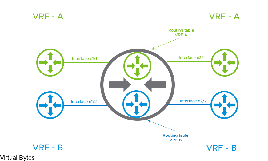
A little about what a VRF is – (Virtual Routing and Forwarding) this allows you to logically carve out a logical router into multiple routers, this allows you to have multiple identical networks but logically segmented off into their own routing instances. Each VRF has its own independent routing tables. this allows to have multiple networks be segmented away from each other and not overlap and still function!
Benefit of NSX-T VRF Lite – allows you to have multple virtual networks on on a same Tier-0 without needing to build a seperate nsx edge node and consuming more resources to just have the ability to segment and isolate a routing instance from another one.
What is : Transport Zone (TZ) defines span of logical networks over the physical infrastructure. Types of Transport Zones – Overlay or VLAN
When a NSX-T Tier-0 VRF is attached to parent Tier-0, there are multiple parameters that will be inherited by design and cannot be changed:
- Edge Cluster
- High Availability mode (Active/Active – Active/Standby)
- BGP Local AS Number
- Internal Transit Subnet
- Tier-0, Tier-1 Transit Subnet.
All other configuration parameters can be independently managed on the Tier-0:
- External Interface IP addresses
- BGP neighbors
- Prefix list, route-map, Redistribution
- Firewall rules
- NAT rules
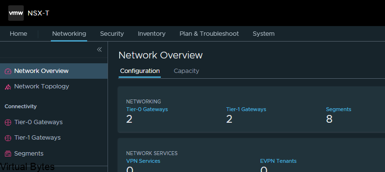
First things first – login into NSX-T Manager, once you are logged in you will have to prepare the network and tranport zones for this VRF lite topology to properly work, as it resides within the overlay network within NSX-T!
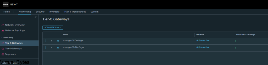
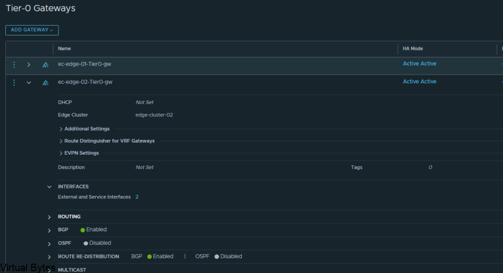
Go to Tier-0 Gateways -> Select one of your Tier-0 Routers that you have configured during initial setup. I will be using my two Tier-0’s, ec-edge-01-Tier0-gw and ec-edge-02-Tier0-gw for this tutorial along with a new Tier-0 VRF which will be attached to the second Tier-0 gateway.
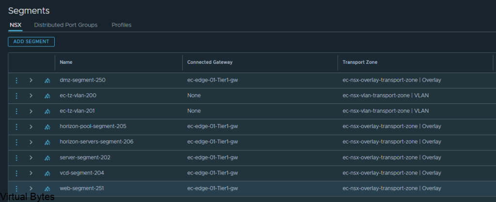
So, first thing we will need to prepare two (2) segments for our VRF T0’s to ride the overlay network.
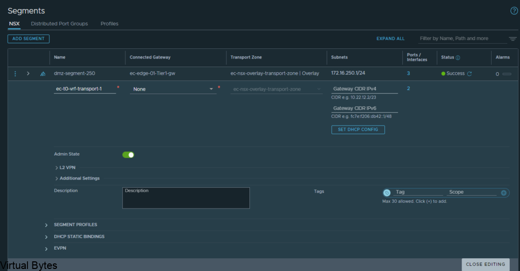
Go to – Segments -> Add a Segment, the two segments will ride the overlay transport zone, no vlan and no gateway attached. Add the segments and click on No for configuring the segment. Repeat for Second segment.
Below is the new segment that will be used for the Transit for the VRF Tier-0.
Just a reminder – this segment will not be connected to any gateway or subnets or vlans
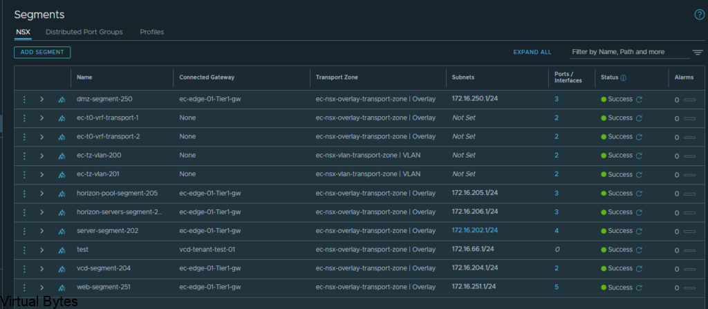
Here are my 2 overlay backed segments, these will traverse the network backbone for the VRF Tier-0 to the ec-edge-01-Tier0-gw.
But, the VRF Tier 0 will be attached to the second Tier 0 (ec-edge-02-Tier0-gw) which is on two seperate Edge nodes (nsx-edge-03, nsx-edge-04) for a Active – Active toplogy.
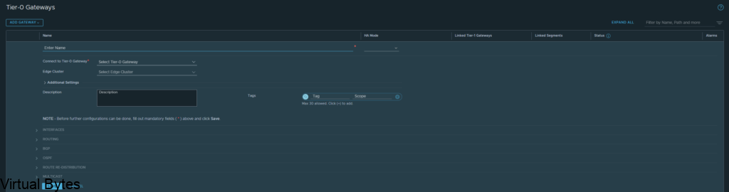
Once the segment has been created then we can go and created a VRF T0. Go back to the Tier-0 Gateway window and click on Add Gateway – VRF ->
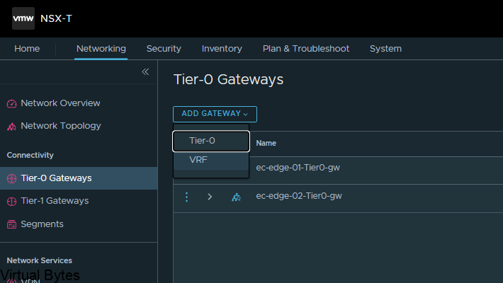
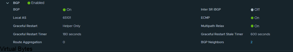
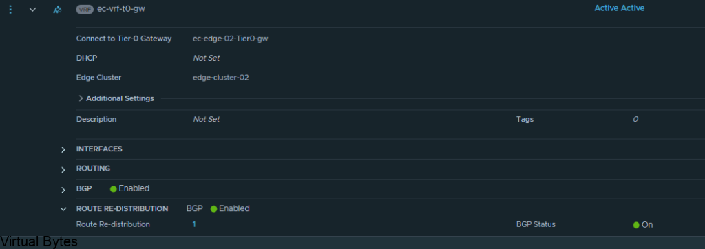
Name of VRF gateway ec-vrf-t0-gw and then attach it to the ec-edge-02-Tier0-gw, enable BGP and create a AS# which i used 65101, and as the second Tier-0-gateway it will act as a ghost router for those VRFs.
Once you finish you will want to click save, and continue configuring that VRF Tier-0, next we will configure the interfaces.
Now, we will need to create interfaces on the ec-edge-01-Tier0-gw. Expand Interfaces and click on the number in blue, for my deployment my NSX-T Tier 0 right now has 2 interfaces.
Once you create the 2 Interfaces on that Tier 0 the number of interfaces will change.
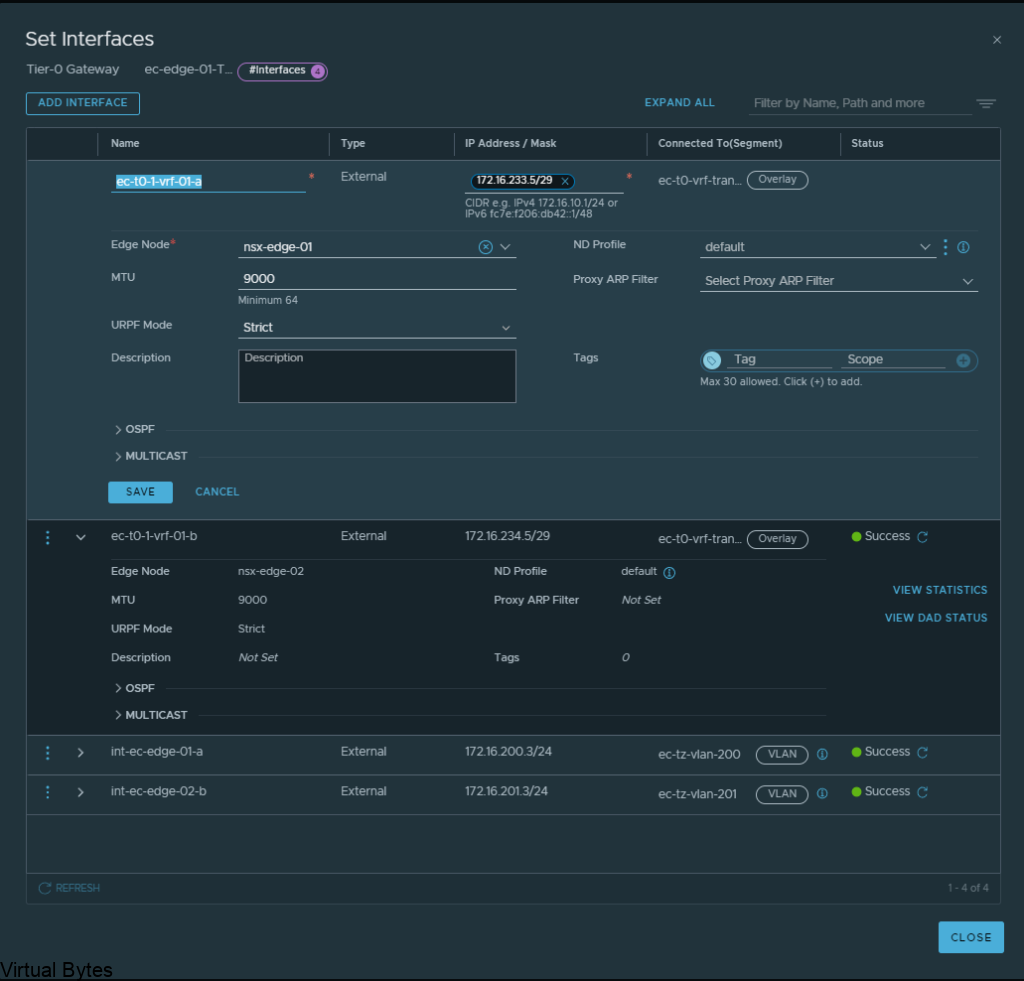
Click on Add Interfaces -> Create a unique name for that first uplink which will peer via BGP with the VRF T0.
Allocate couple IP addresses, I am using 172.16.233.5/29 for the first interface on the ec-vrf-t0-gw, which lives within the nsx-edge-01 for my deployment, the VRF T0 will have 172.16.233.6/29, and connect that interface on the overlay segment you created earlier.
Then the second interface, I created with the IP of 172.16.234.5/29, also the VRF Tier-0 will have 172.16.234.6/29 and each interface will be attaced to that second nsx-edge-node-02, so first IP 172.16.233.5/29 is attached to edge node 1 and second IP will be on Edge Node 02.
ec-t0-1-vrf-01-a – 172.16.233.5/29 – ec-t0-vrf-transport-1 172.16.233.6/29 (overlay segment)
ec-t0-1-vrf-01-b 172.16.234.5/29 – ec-t0-vrf-transport-2 172.16.234.6/29 (overlay segment)
Jumbo Frames 9000 MTU on both interfaces
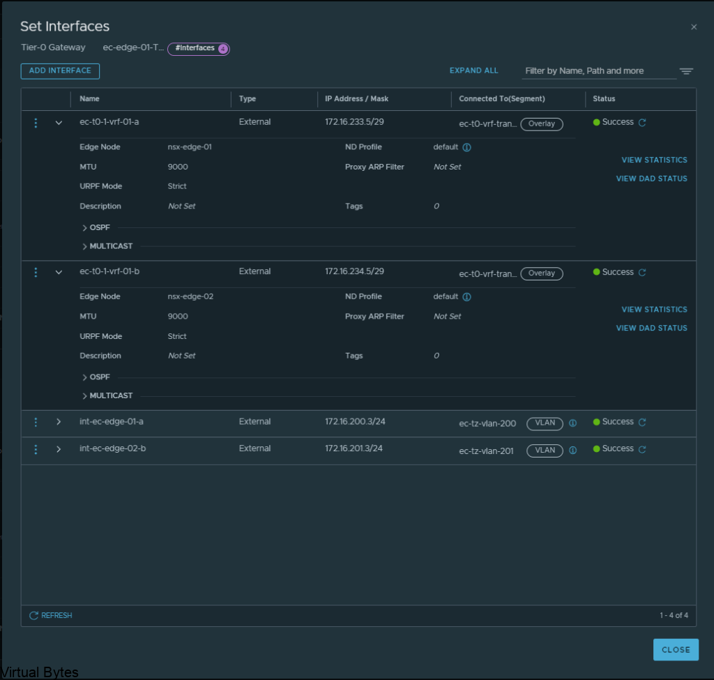
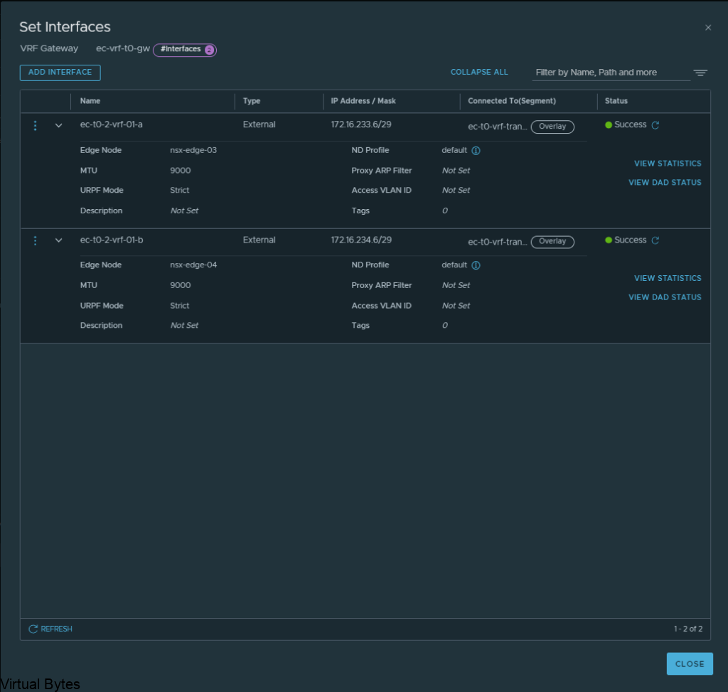
Once you have created all required interfaces, below is an example of what i created, make sure you have everything setup correctly or the T0 and VRF T0 will not peer up!
Then go to BGP configuration for that nsx-edge-01 and nsx-edge-02 and prepare the peers from it to the VRF Tier-0 router.
Next, we will create another set of interfaces for the VRF T0 itself, these will live on nsx-edge-03 and nsx-edge-04. Same steps as what we created for nsx-edge-01 and nsx-edge-02, just flip it!
ec-t0-1-vrf-01-a – 172.16.233.6/29 – nsx-edge-03
ec-t0-1-vrf-01-b -172.16.234.6/29 – nsx-edge-04
Jumbo Frames 9000MTU
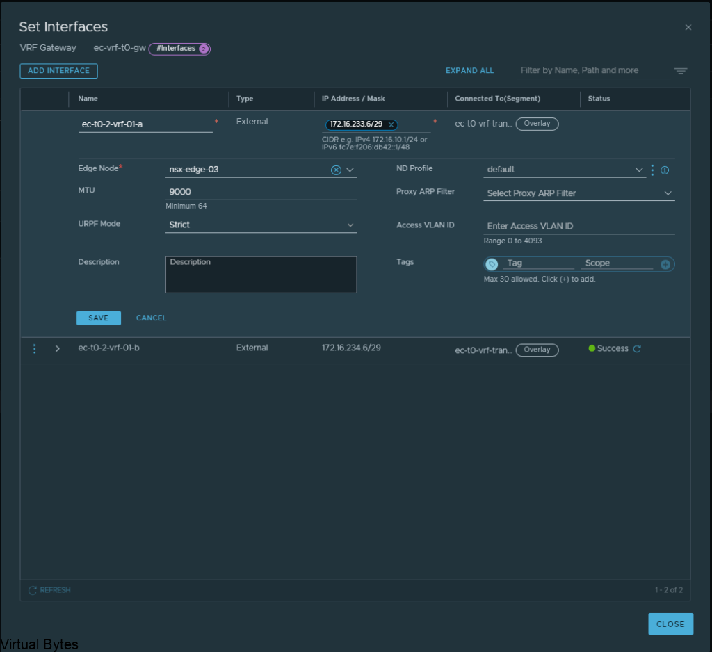
Once, both interfaces are configured for the Tier-0’s, you should have two interfaces with different subnets for the transit between the VRF T0 and the Edge 01 gateway Tier-0. After, interfaces are created on the specific nsx-edges.
Verify the interfaces and the correct segments and if everything is good, click save and proceed to next step.
Everything we just created rides the overlay segments, now we will configure BGP on each of the T0s.
Expand BGP – Click on the External and Service Interfaces (number) mine has 2.
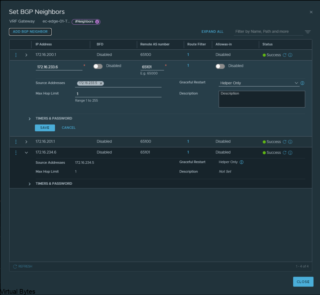
Click Edit on the Tier 0, ec-edge-01-Tier0-gw and expand BGP and click on BGP Neigbors.
Create the BGP Peers on the VRF T0, you will see the interface IP we created earlier under the “Source Addresses” those are attached to each specific interface which is on those overlay segments we created for the VRF lite model.
172.16.233.5 – 172.16.233.6 – nsx-edge-03
172.16.234.5 – 172.16.234.6 – nsx-edge-04
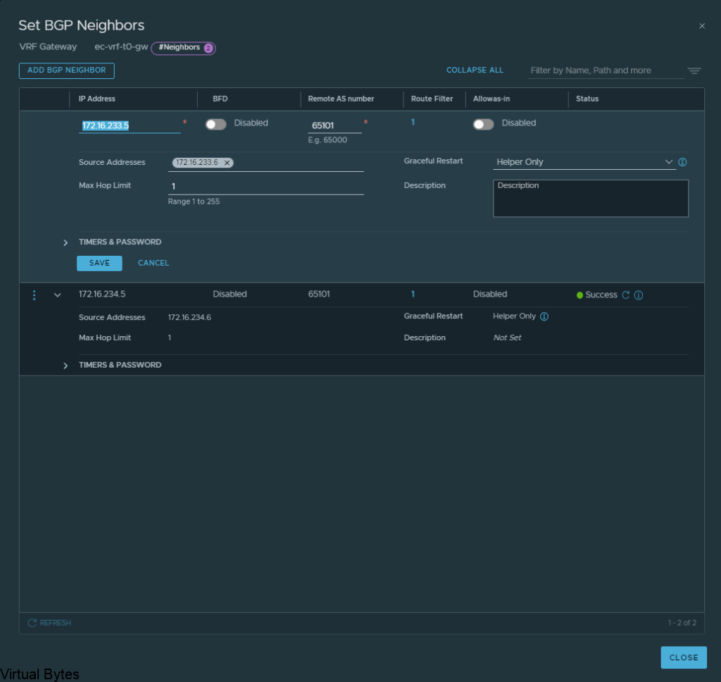
Click Save and proceed to creating the second BGP interface which will be for nsx-edge-04 BGP
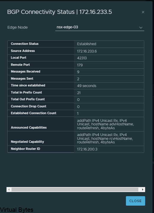
If everything went smooth, you should be able to verify your BGP peers between both Tier-0 and VRF Tier-0 as shown below.
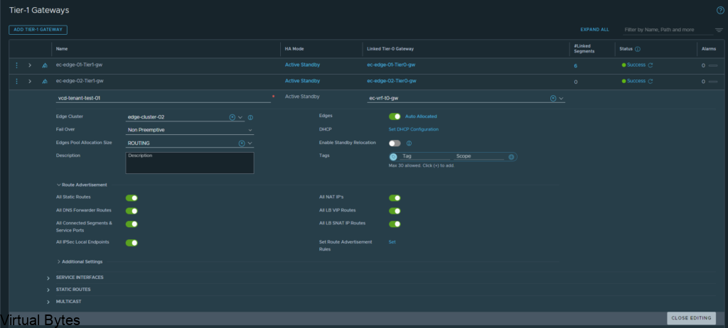
After you have created the networks, you may create a T1 and attach it to that VRF T0! Which you can consume within VMware Cloud Director or just a standalone T1 which is attached to that VRF, But next we will attach a test segment to this VRF T0 we just created!
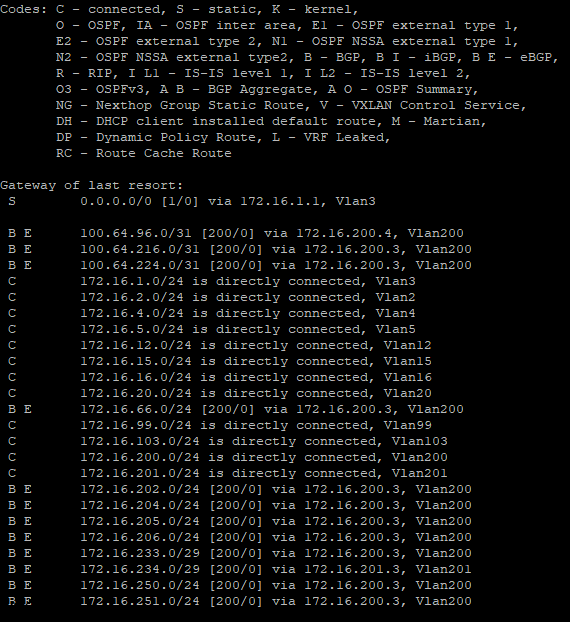
Once you create that segment with a subnet attached to the Tier-1 you will want to verify if you have any routes being advertised within your TOR Router, for my lab i am using a Arista DCS 7050QX-F-S which is running BGP.
I ran a command – show ip route on my Arista core switch.
You will see many different routes but the one we are intersted is 172.16.66.0/24 we just advertised.
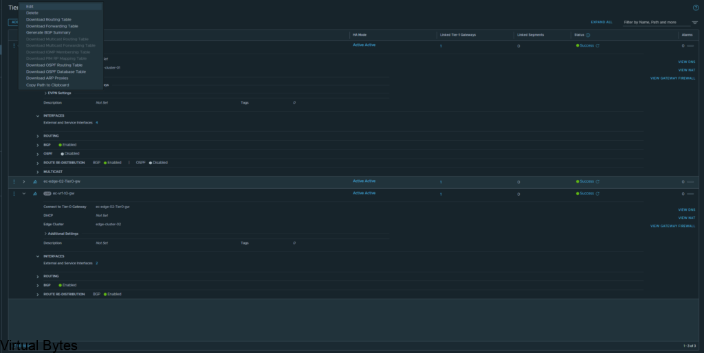
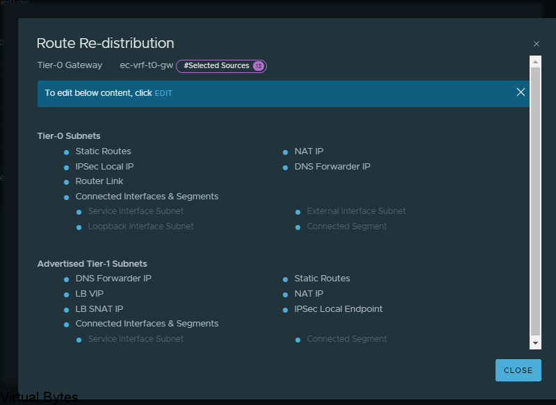
If you do not see any routes coming up from the new VRF T0 we created you will want to create a Route-Redistrubition for that T0, click on the vrf t0 and edit and go to Route Re Distribution
For the walkthrough I redistributed everything for testing purposes, but for your use case you will only want to re-distribute the specific subnets, nats, forward IPs etc.
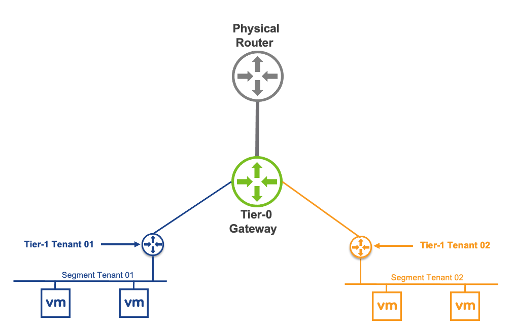
Overall toplogy of what we created is to the left with the two T0s, the T0 to the right is my current infrastructure.
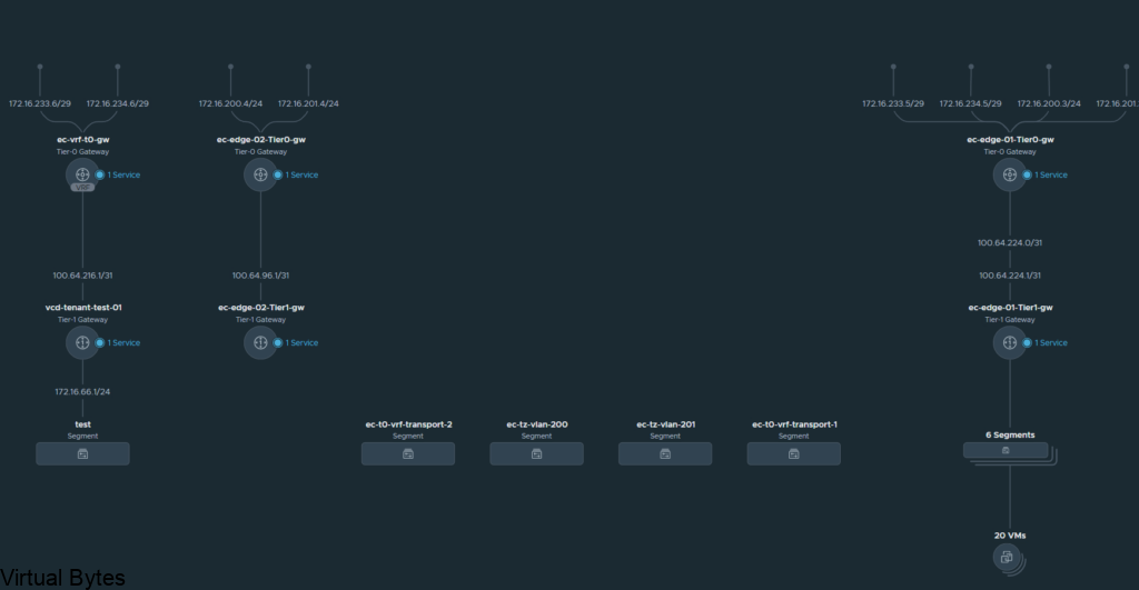
That is it! For this walk through, we created a VRF T0 and attached it to the second edge t0 router and then we took the VRF T0 and peered up to the ec-edge01-t0-gw.