Todays topic is deploying VMware Cloud Director Availability for VMware Cloud Director! Todays topic is deploying VMware Cloud Director Availability for VMware Cloud Director! This walkthrough will guide you on how to deploy VCDA from a OVA to an working appliance. All this is created within my home lab. A different guide will be on how to setup VCDA and multi VCDs to create a Peer between and show some Migrations and so on! 🙂
A little about VCDA! – From VMware’s site
VMware Cloud Director Availability™ is a Disaster Recovery-as-a-Service (DRaaS) solution. Between multi-tenant clouds and on-premises, with asynchronous replications, VMware Cloud Director Availability migrates, protects, fails over, and reverses failover of vApps and virtual machines. VMware Cloud Director Availability is available through the VMware Cloud Provider Program.VMware Cloud Director Availability introduces a unified architecture for the disaster recovery and migration of VMware vSphere ® workloads. With VMware Cloud Director Availability, the service providers and their tenants can migrate and protect vApps and virtual machines:
- From an on-premises vCenter Server site to a VMware Cloud Director™ site
- From a VMware Cloud Director site to an on-premises vCenter Server site
- From one VMware Cloud Director site to another VMware Cloud Director site
Cloud SiteIn a single cloud site, one VMware Cloud Director Availability instance consists of:
- One Cloud Replication Management Appliance
- One or more Cloud Replicator Appliance instances
- One Cloud Tunnel Appliance
Links!
Replication Flow – Link to VMware
- Multiple Availability cloud sites can coexist in one VMware Cloud Director instance. In a site, all the cloud appliances operate together to support managing replications for virtual machines, secure SSL communication, and storage of the replicated data. The service providers can support recovery for multiple tenant environments that can scale to handle the increasing workloads.
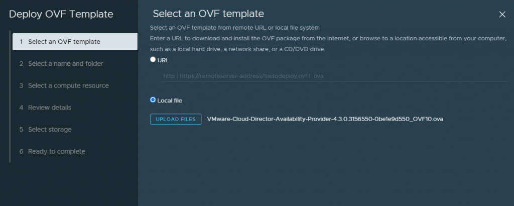
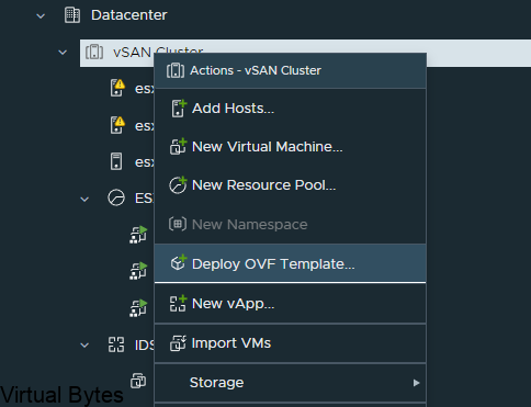
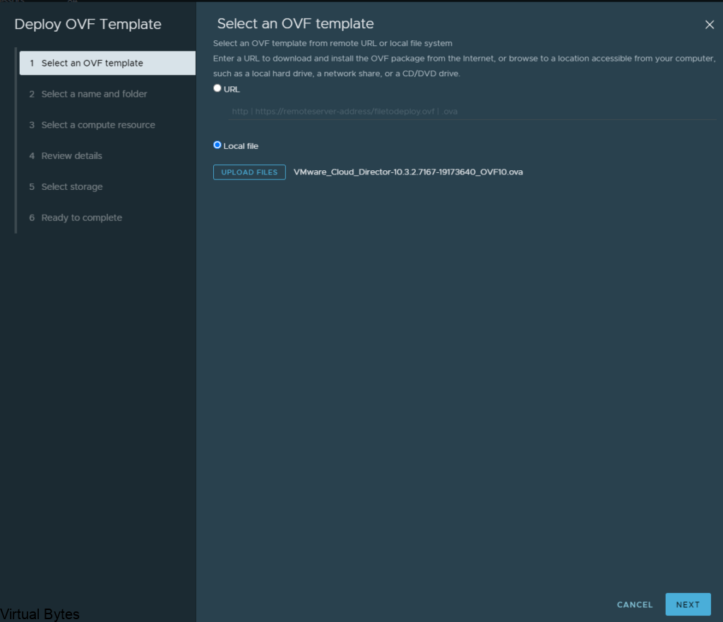
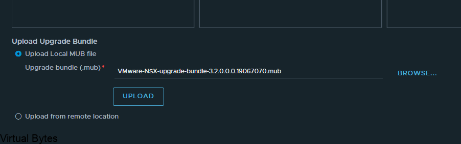
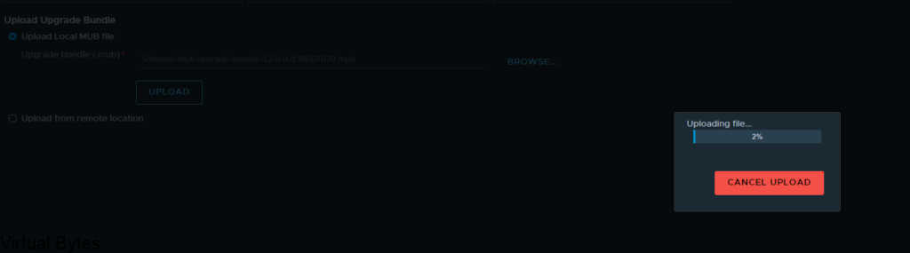
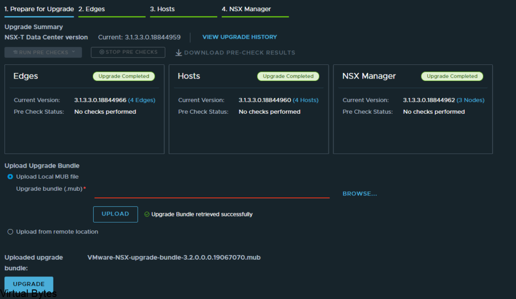
Upload the OVA for VCDA
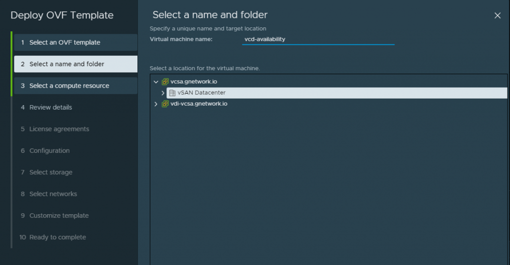
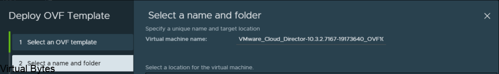
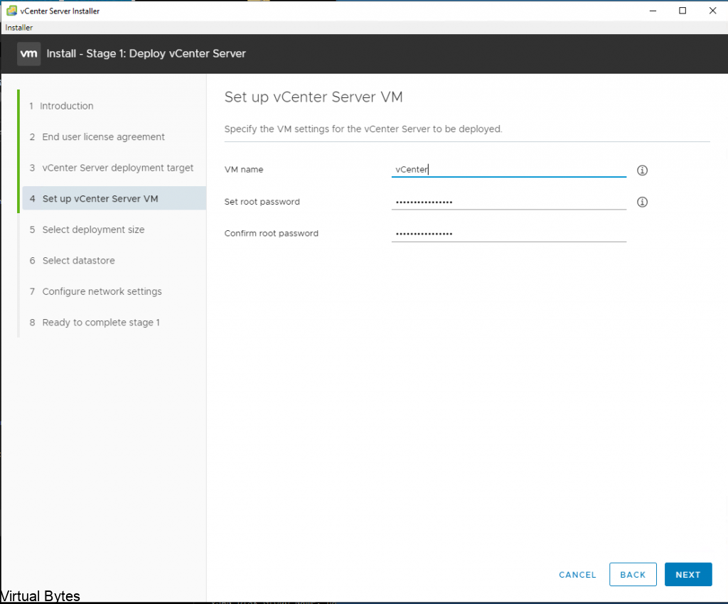
Create a friendly name within this deployment, i like to create a name that is meaningful and corellates to a service.
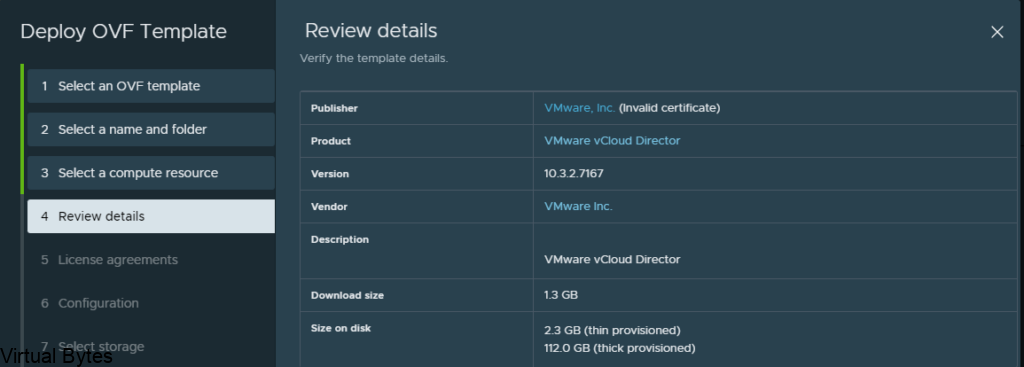
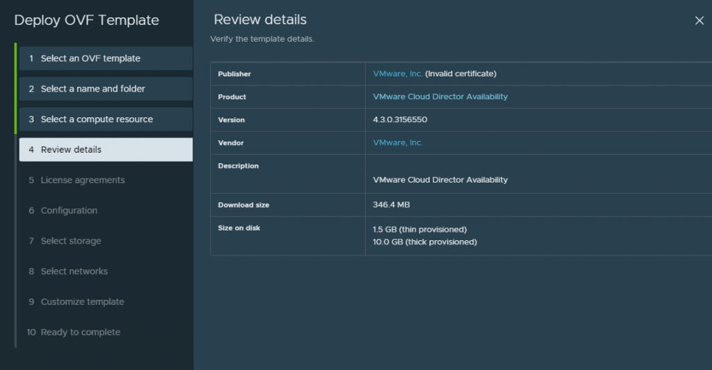
Proceed to step 4
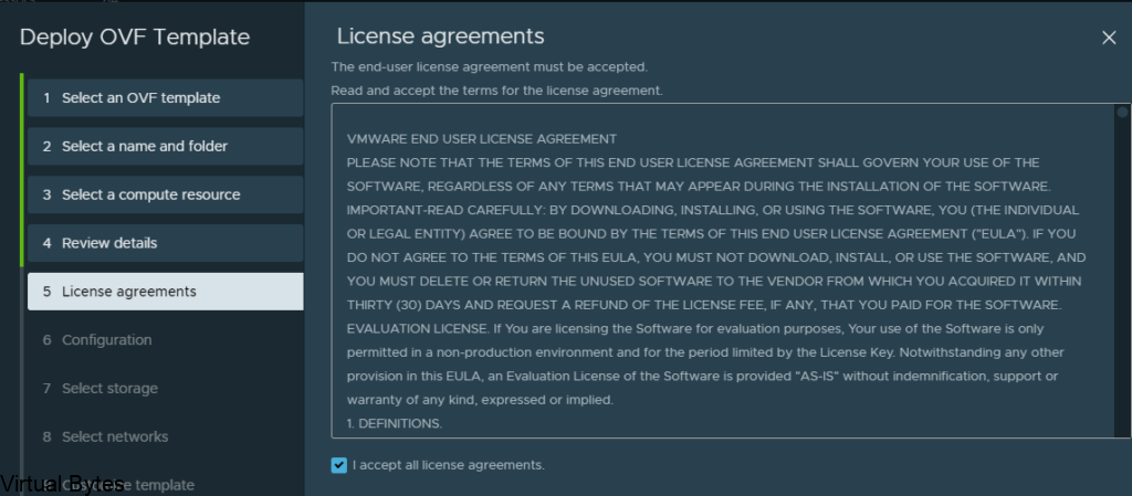
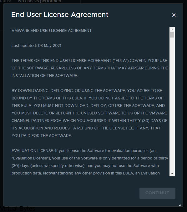
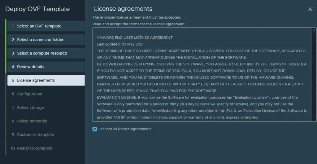
Accept this lovely EULA 😛
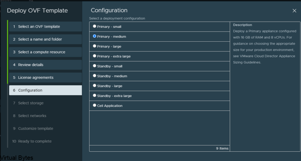
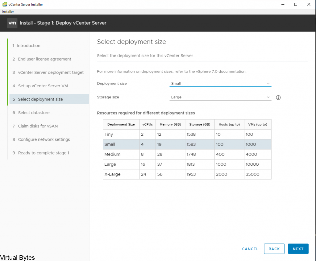
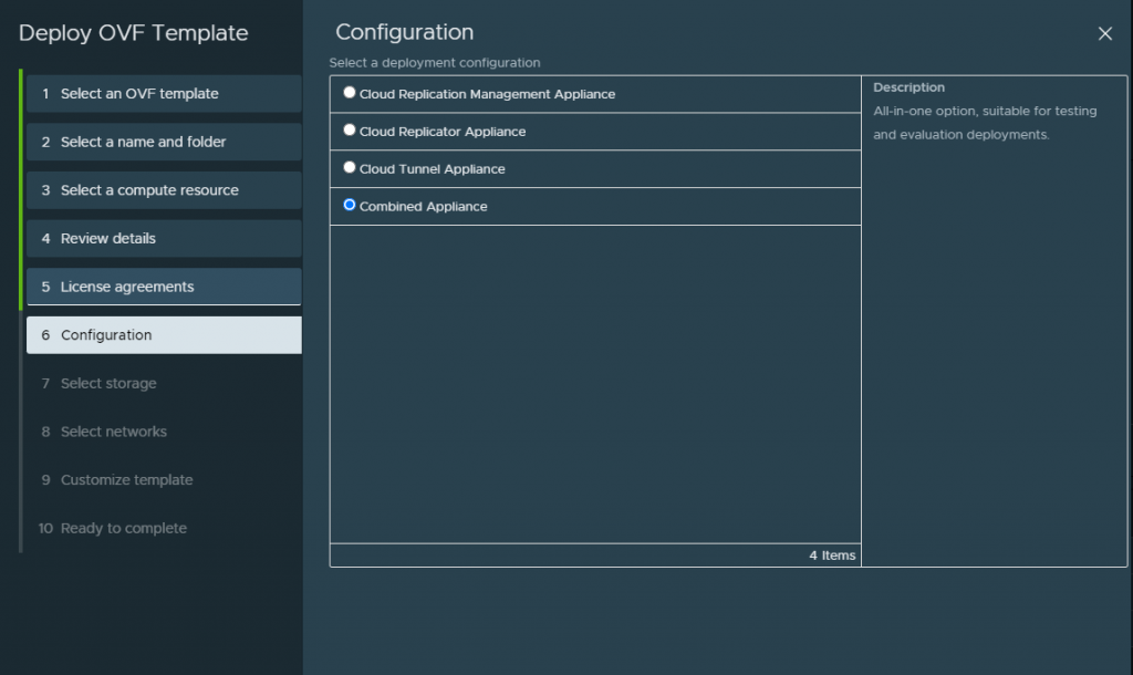
Since in my lab for this deployment i did a combined appliance. I will also do a seperate applaince for each service configuration.
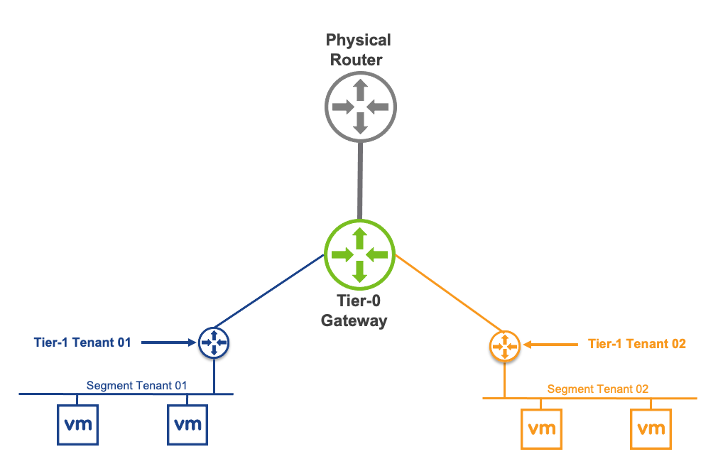
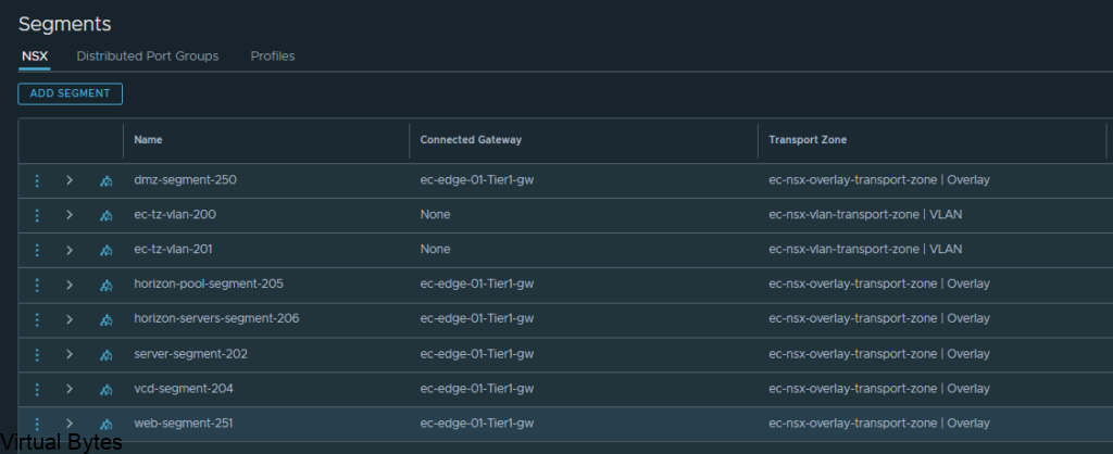
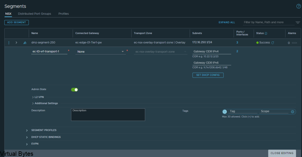
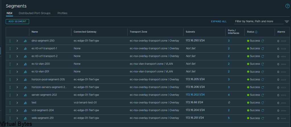
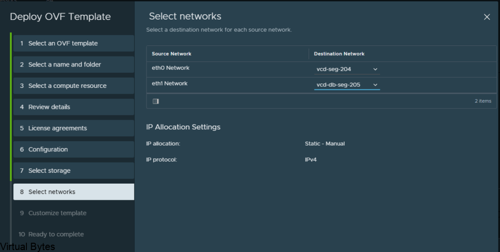
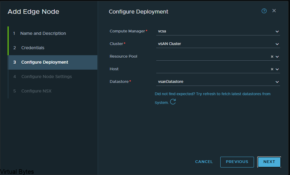
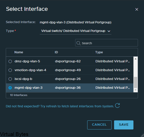
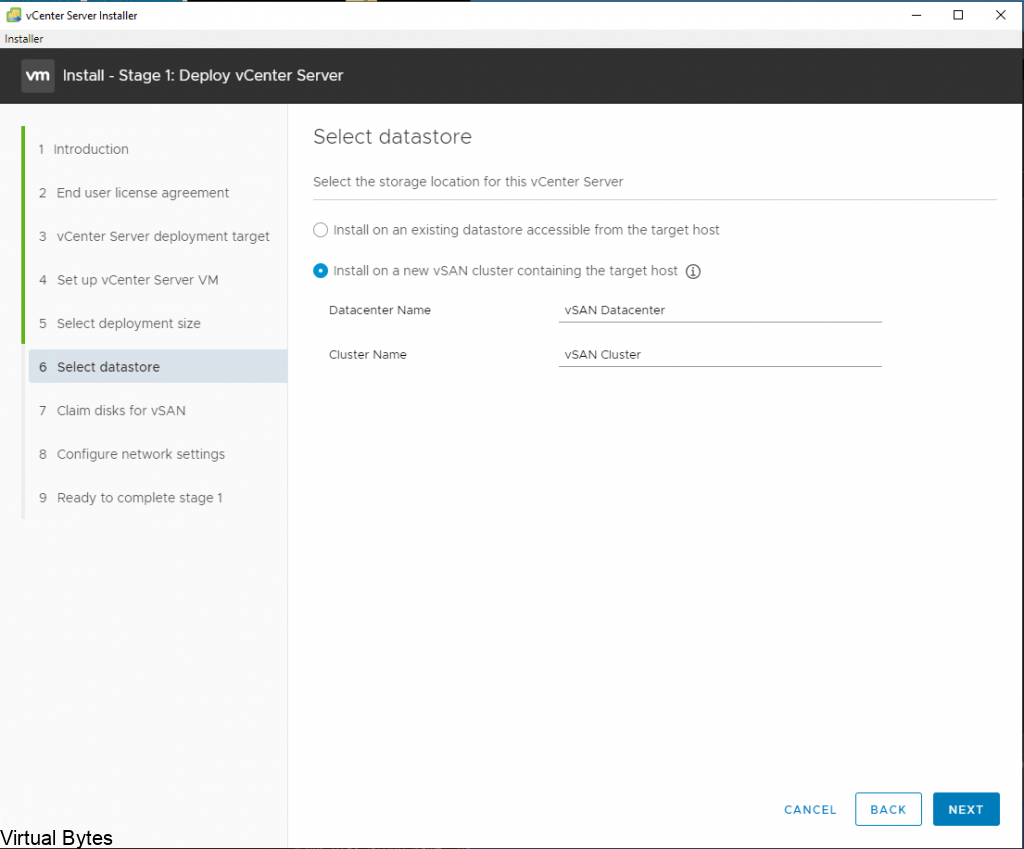
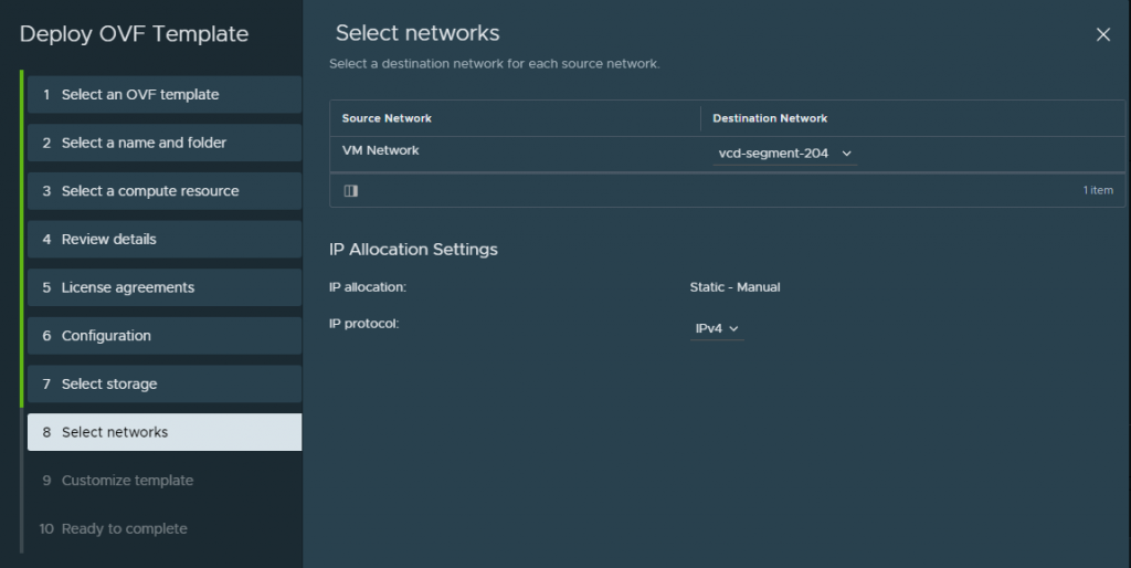
Choose the network segment you will have your VCDA appliance live on, i put my appiliance on a NSX-T backed segment on the overlay network.
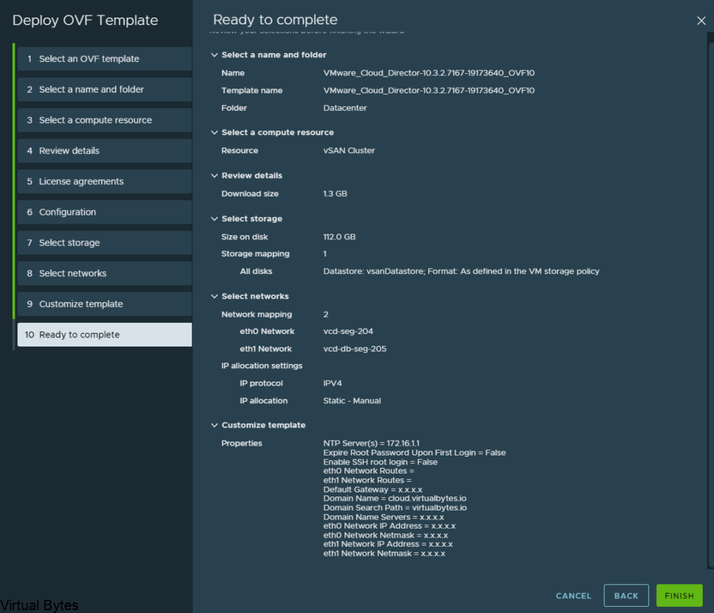
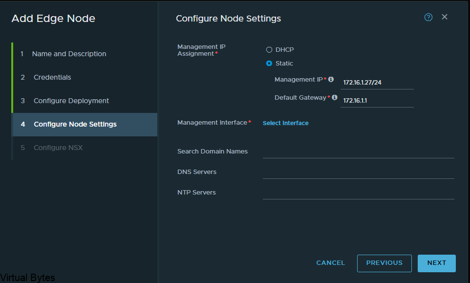
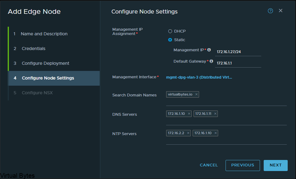
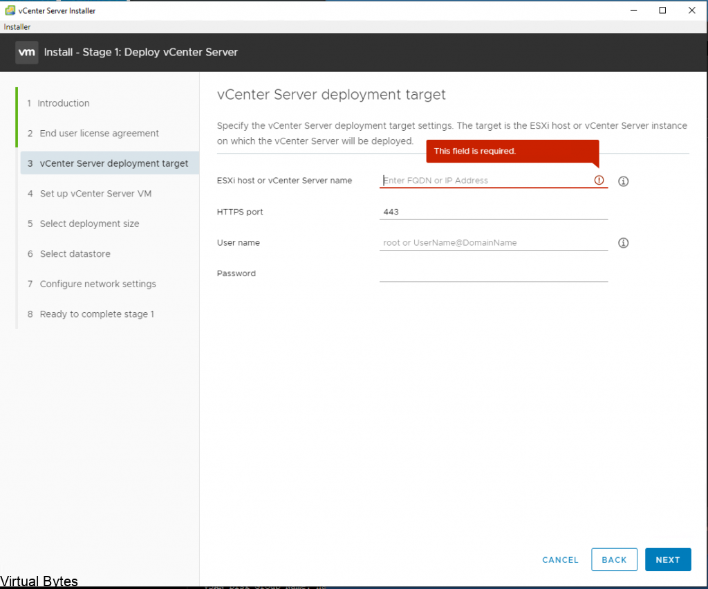
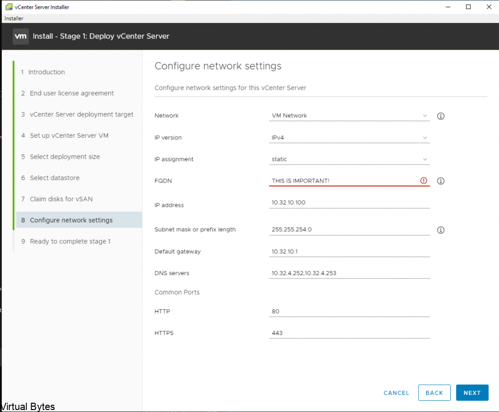
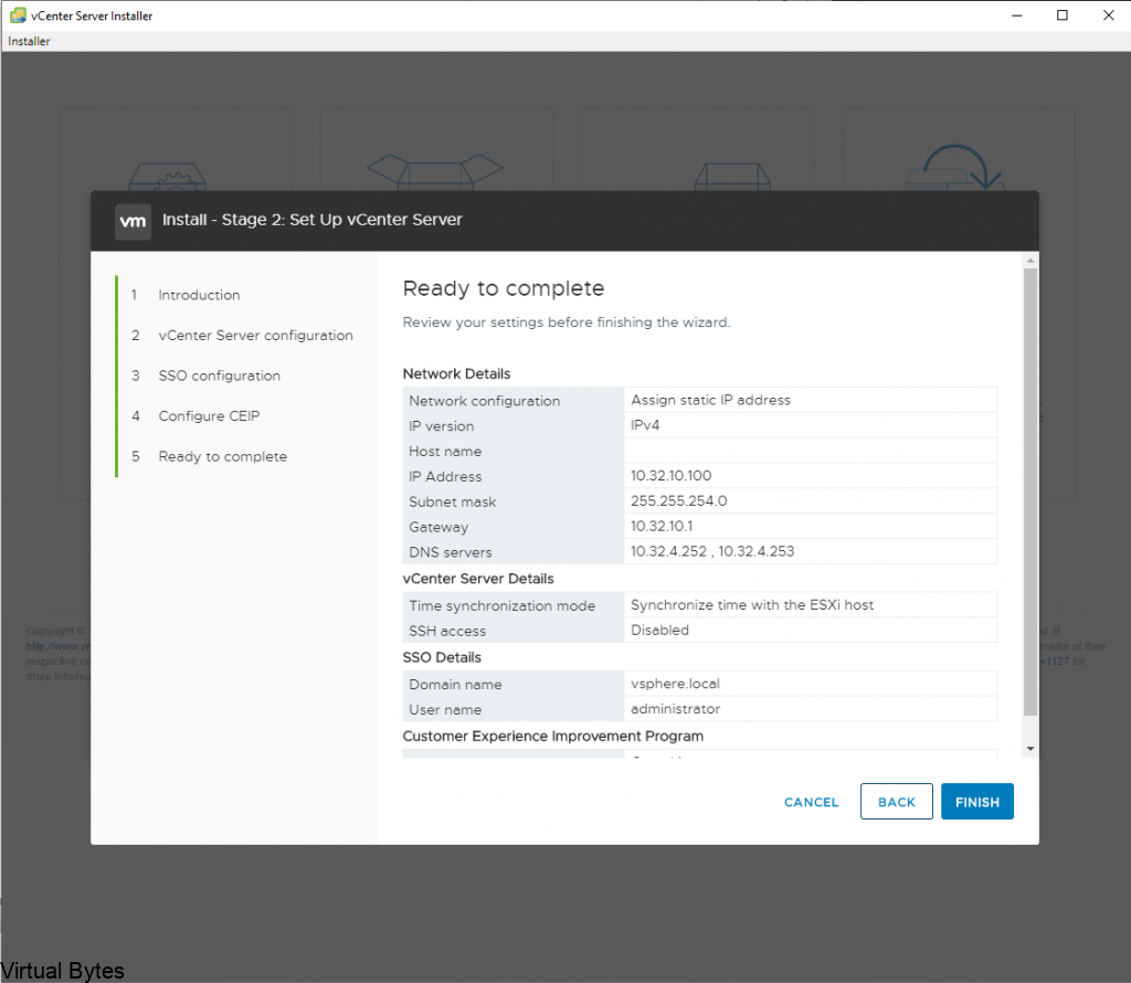
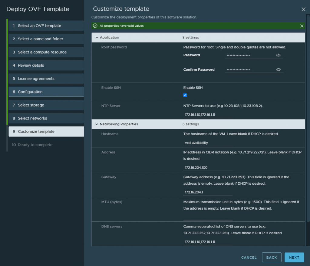
Fill in the required information, also create an A record for the VCDA appliance so that when it does its recersive DNS it will succesffuly generate a self signed certificate and allow the appliance to keep building, successfuly.
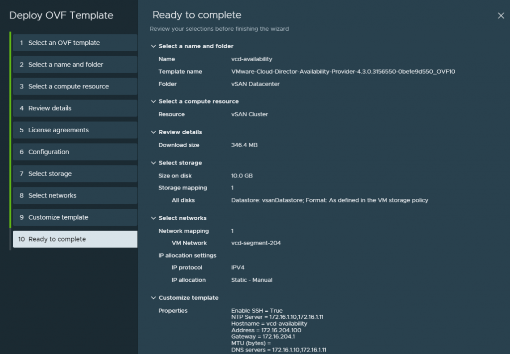
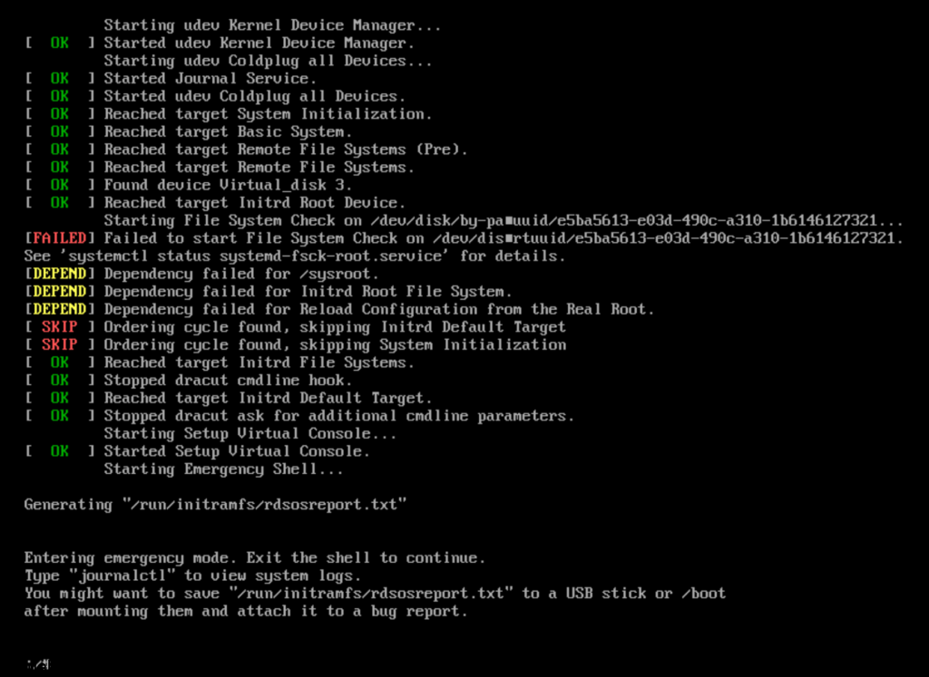
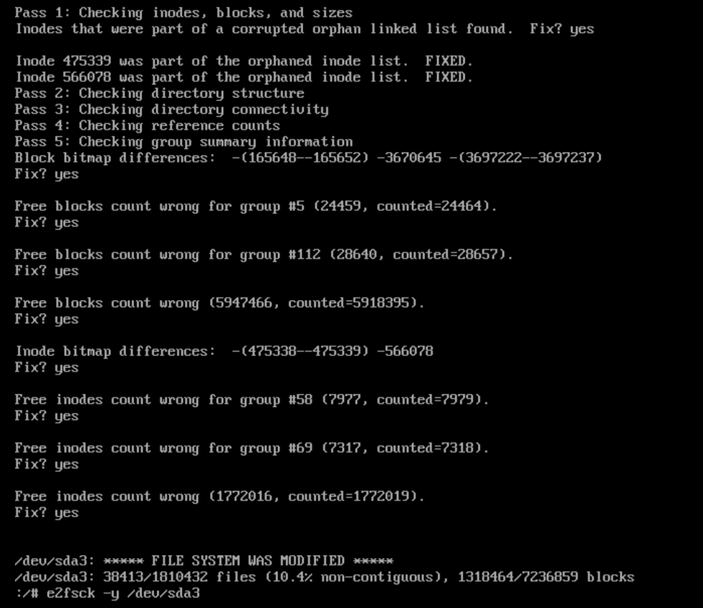
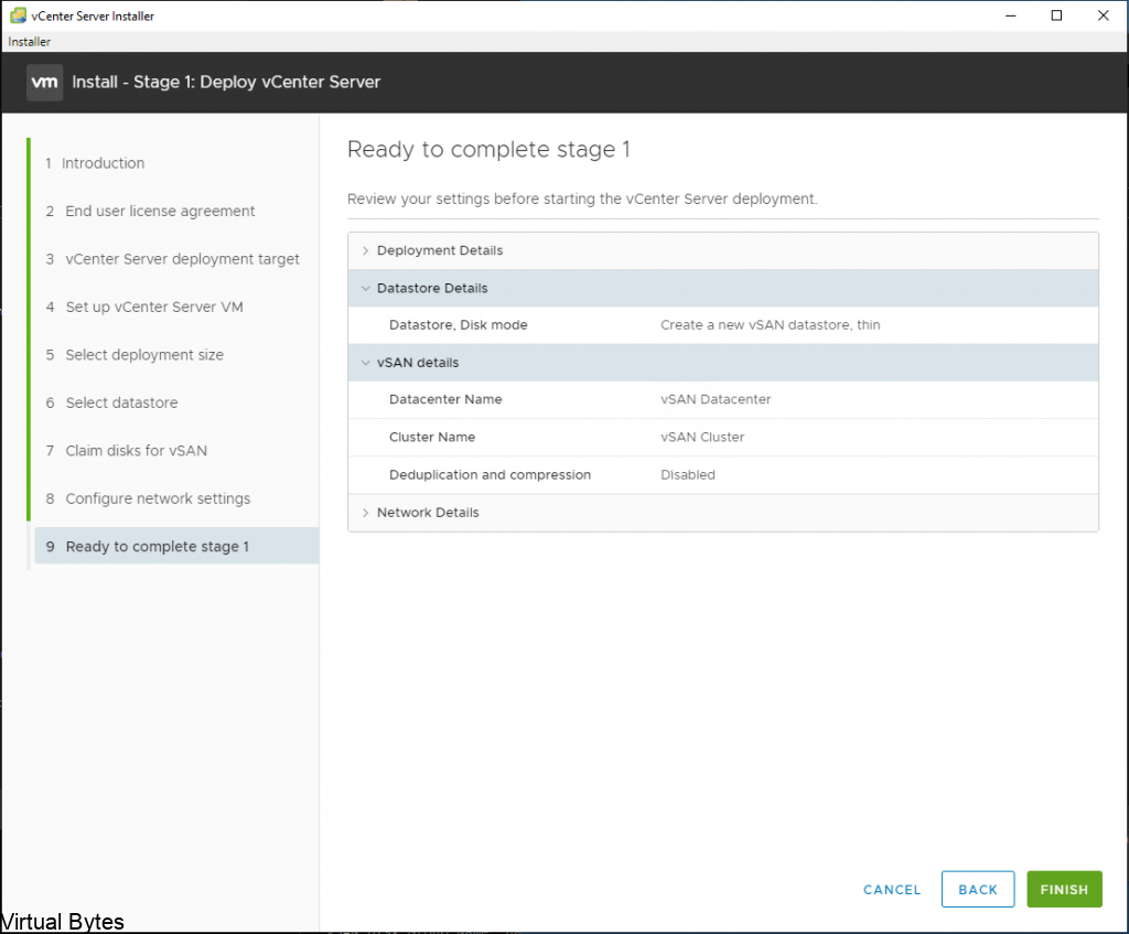
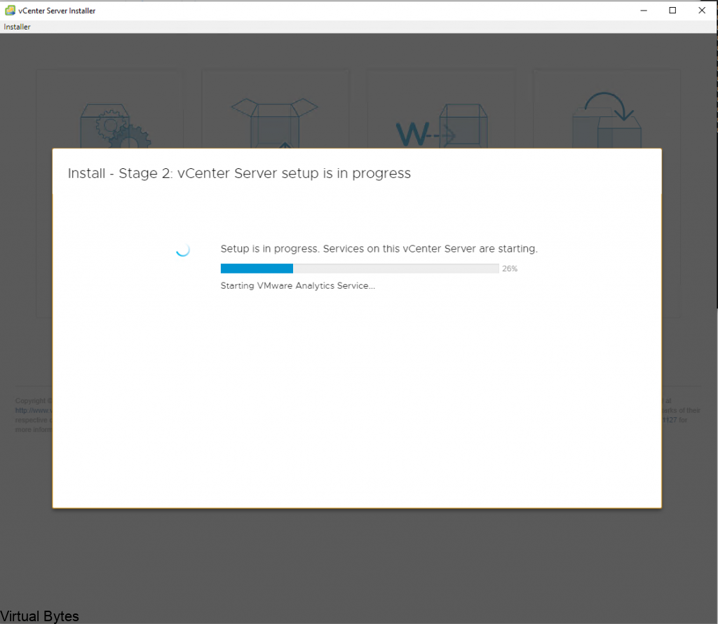
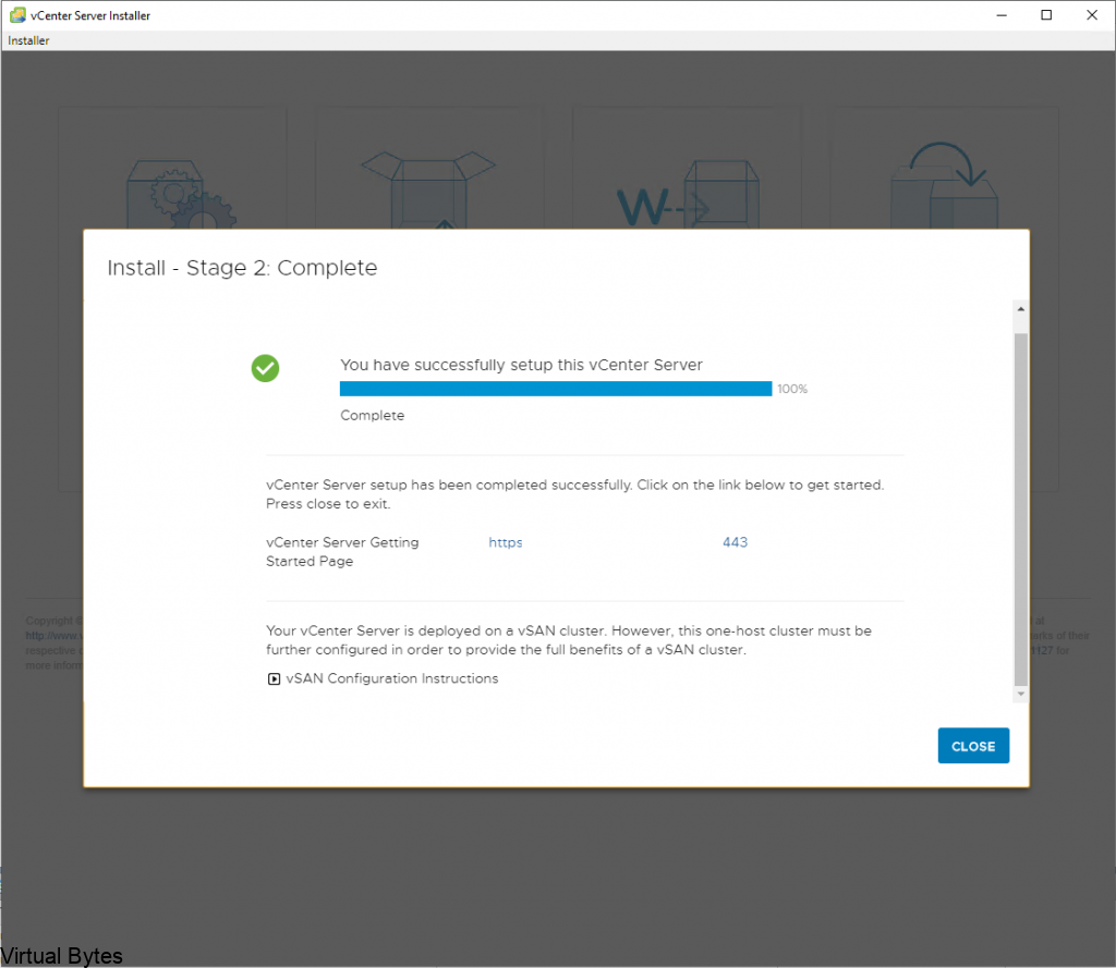
After you hit submit and watch the deployment you can open the vmware web / remote console and just watch for any issues or errors that may cause the deployment to fail.
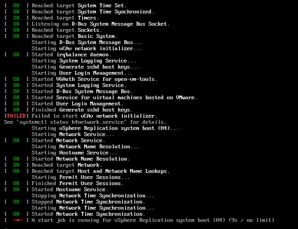
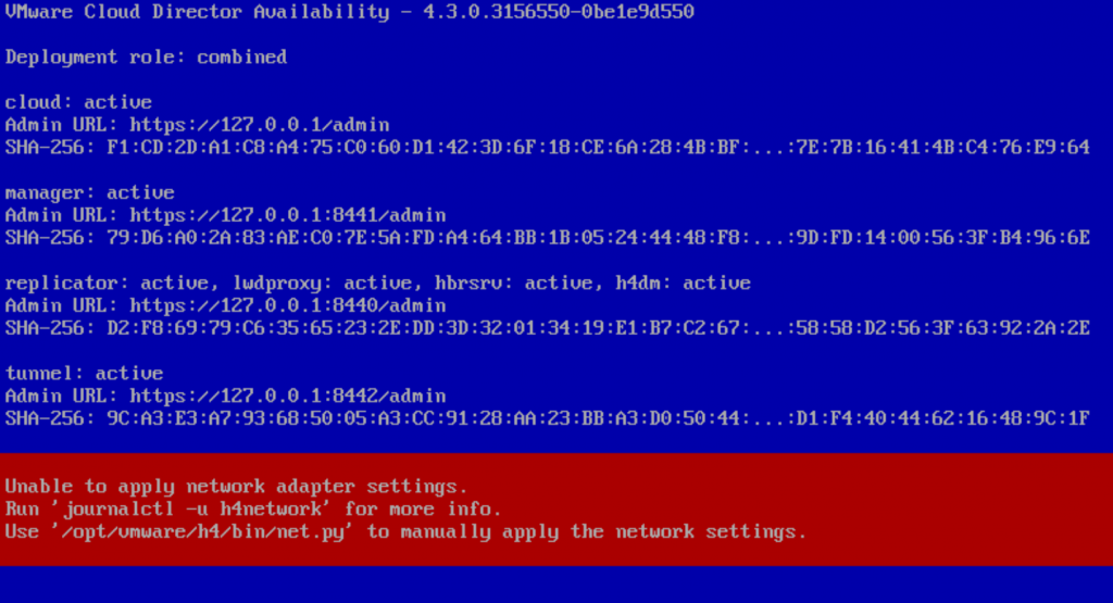
I ran into a snag! What happened was the network configuration did not accept all the information i filled in for the network adapter on the VCDA appliance OVA deployment. So here, I had to login as root into the VCDA appliance, it did force me to reset the password that I orginally set on the OVA deployment.
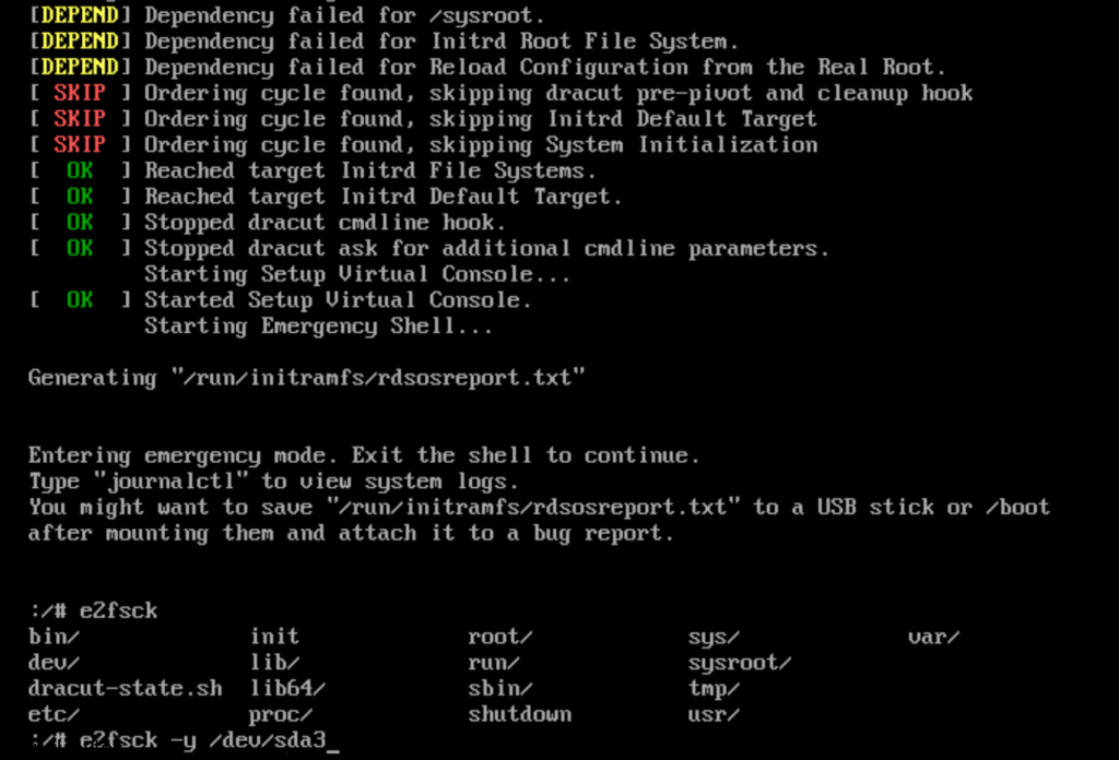
Connect to the VMware Cloud Director Availability by using a Secure Shell (SSH) client.
Open an SSH connection to Appliance-IP-Address.
Log in as the root user.
To retrieve all available network adapters, run: /opt/vmware/h4/bin/net.py nics-status
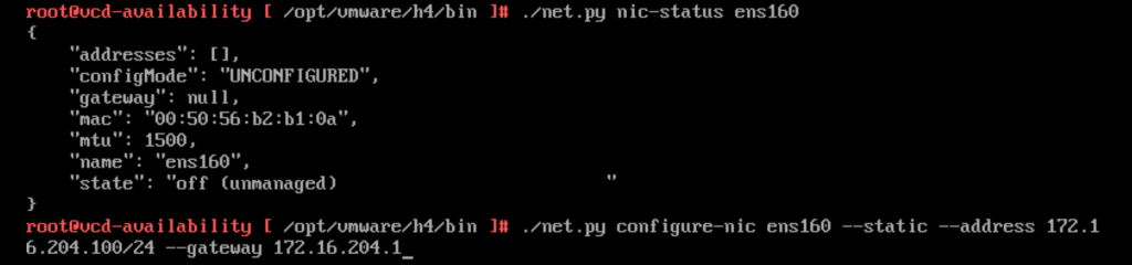
/opt/vmware/h4/bin/net.py nic-status ens160
/opt/vmware/h4/bin/net.py configure-nic ens160 — static –address 172.16.204.100/24 –gateway 172.16.204.1
After you have updated all the network configuration you can check the config by :
To retrieve the status of a specific network adapter,
/opt/vmware/h4/bin/net.py nic-status ens160
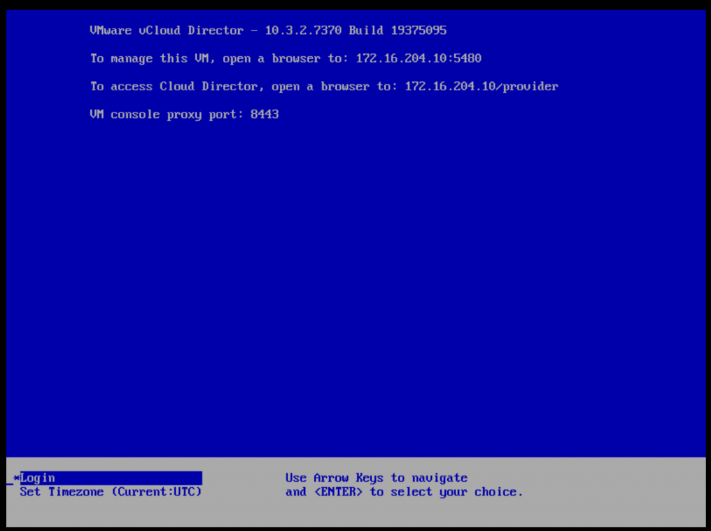
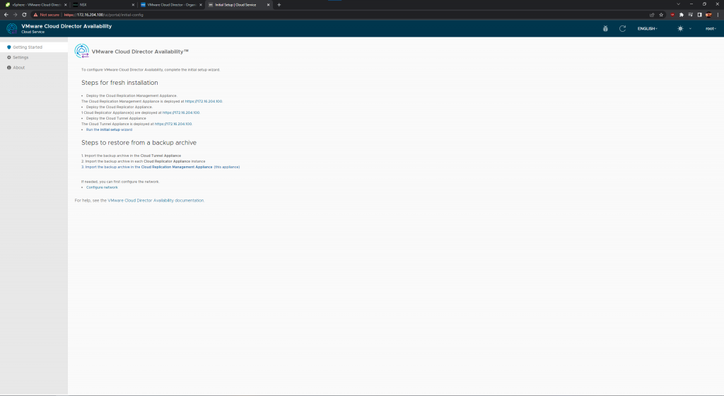
After the networking is all good, then you may go back to your web browser and go to the UI of the VCDA. Here we will configure next few steps.
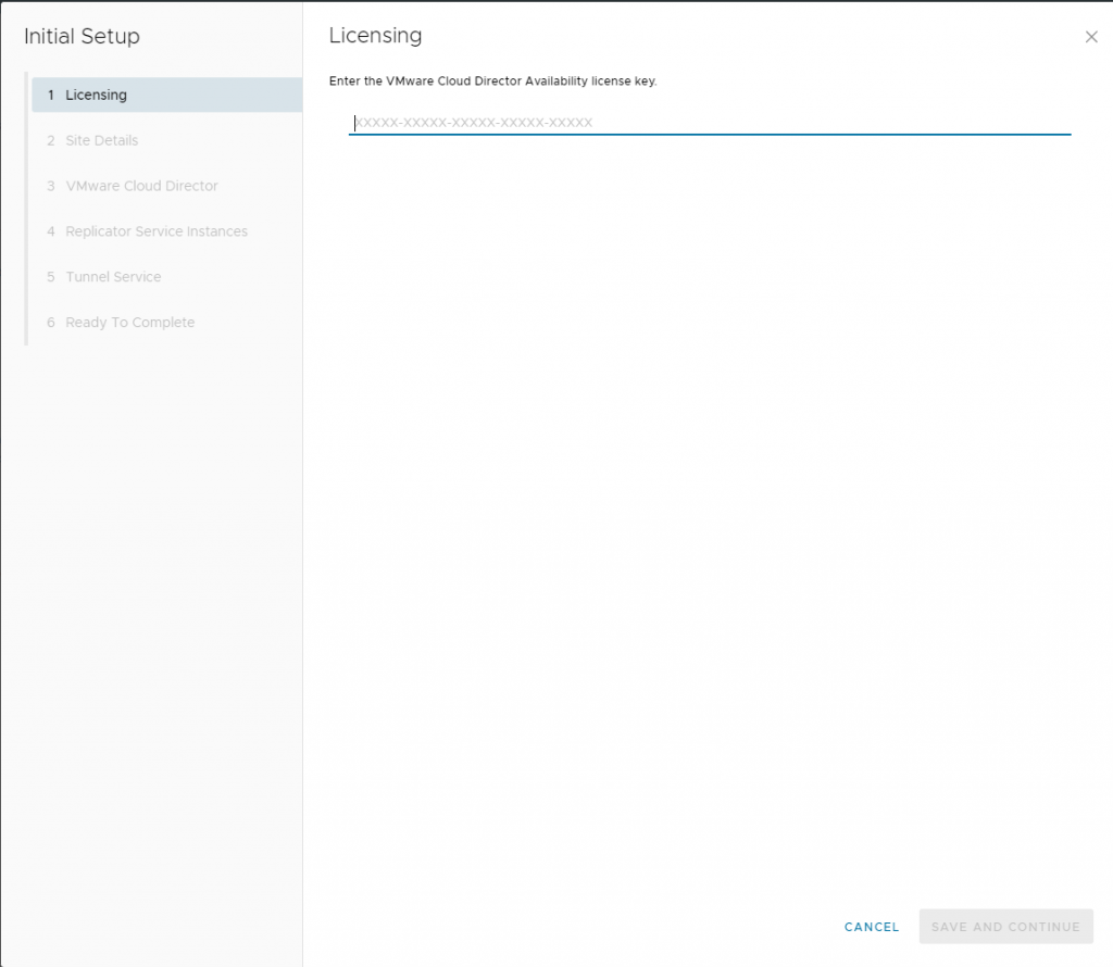
Add the license you have recived for VCDA – this license is different than what VMware Cloud Director utilizes.
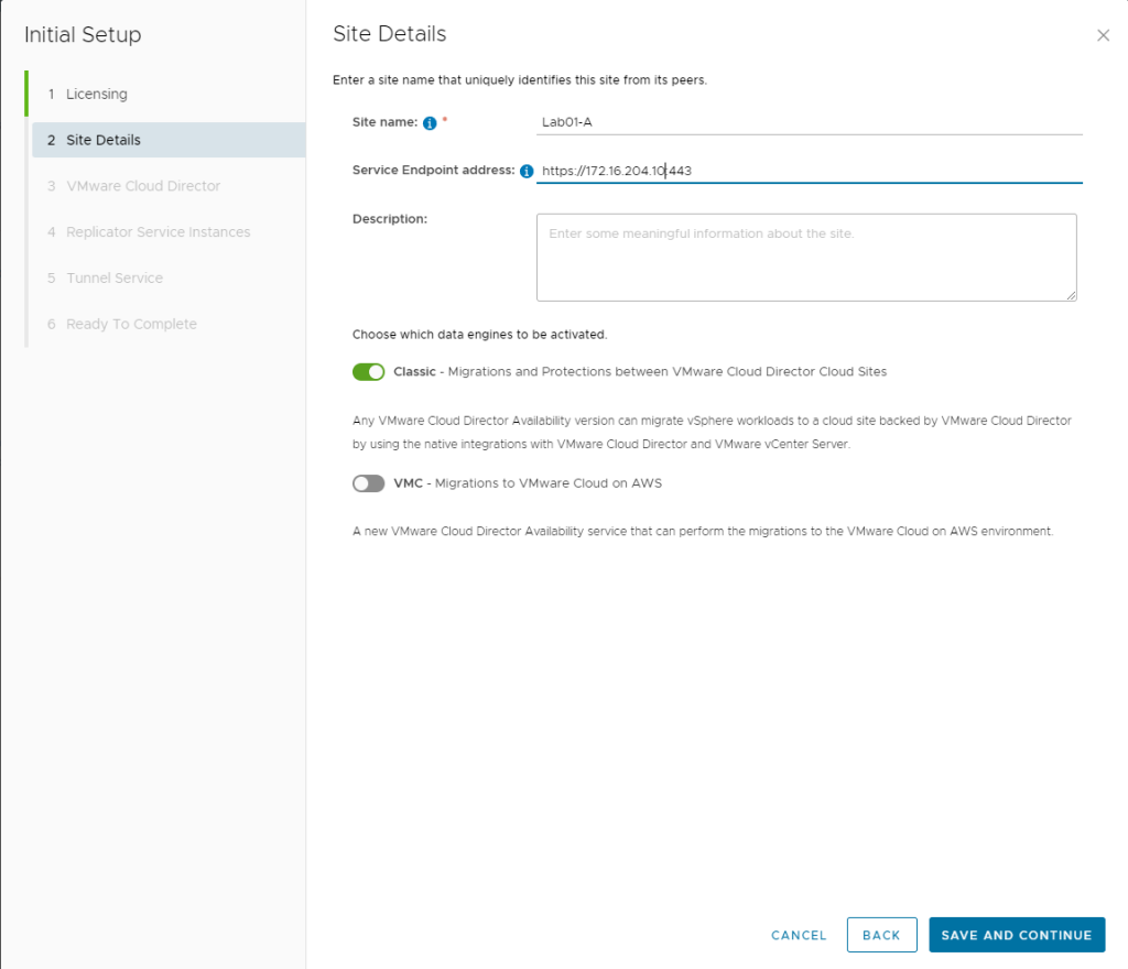
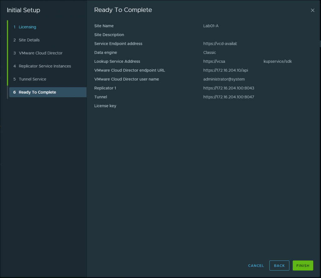
Configure the Site Details for your VCDA. I did Classic data engines since I do not have VMware on AWS.
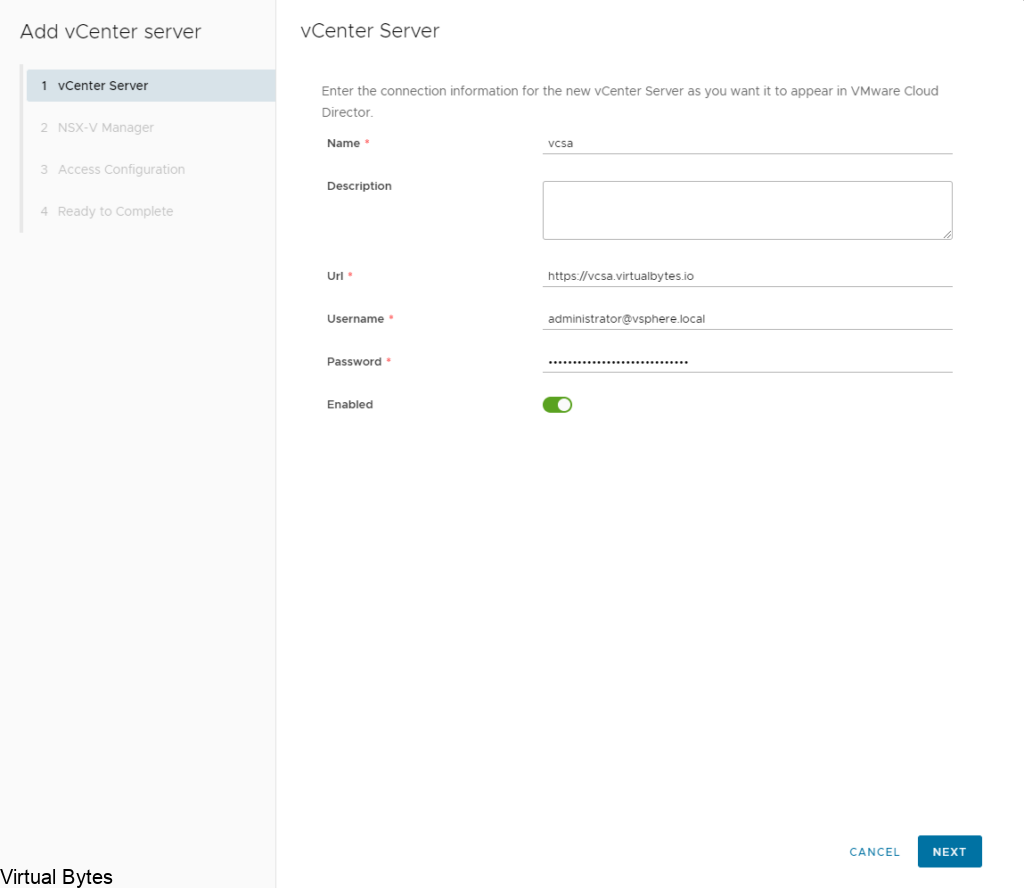
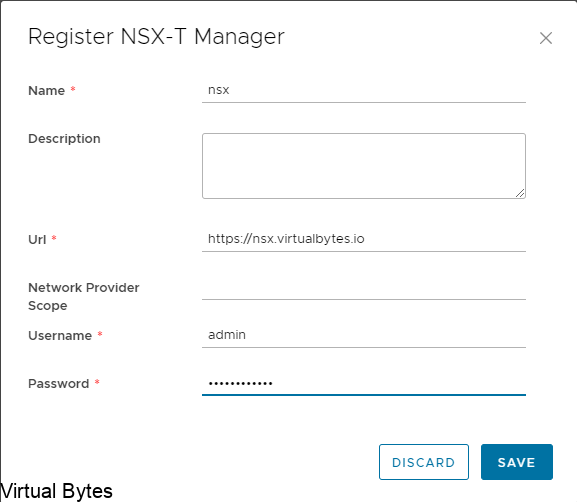
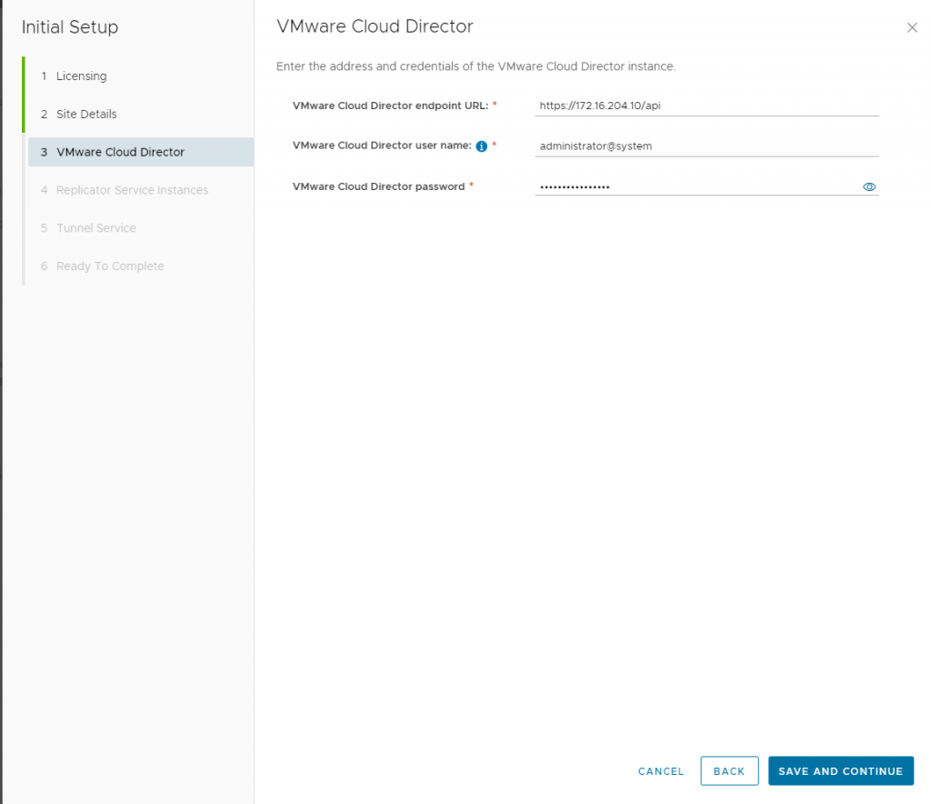
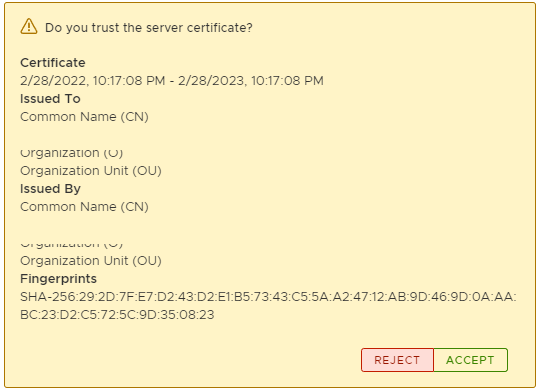
Add your first VMware Cloud Director to this next step
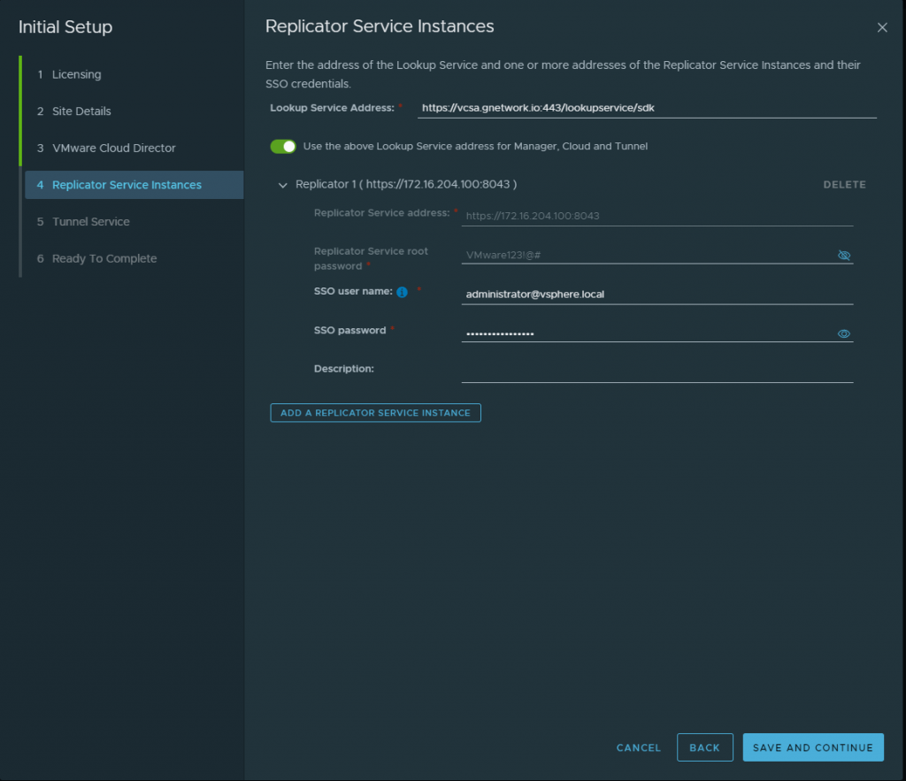
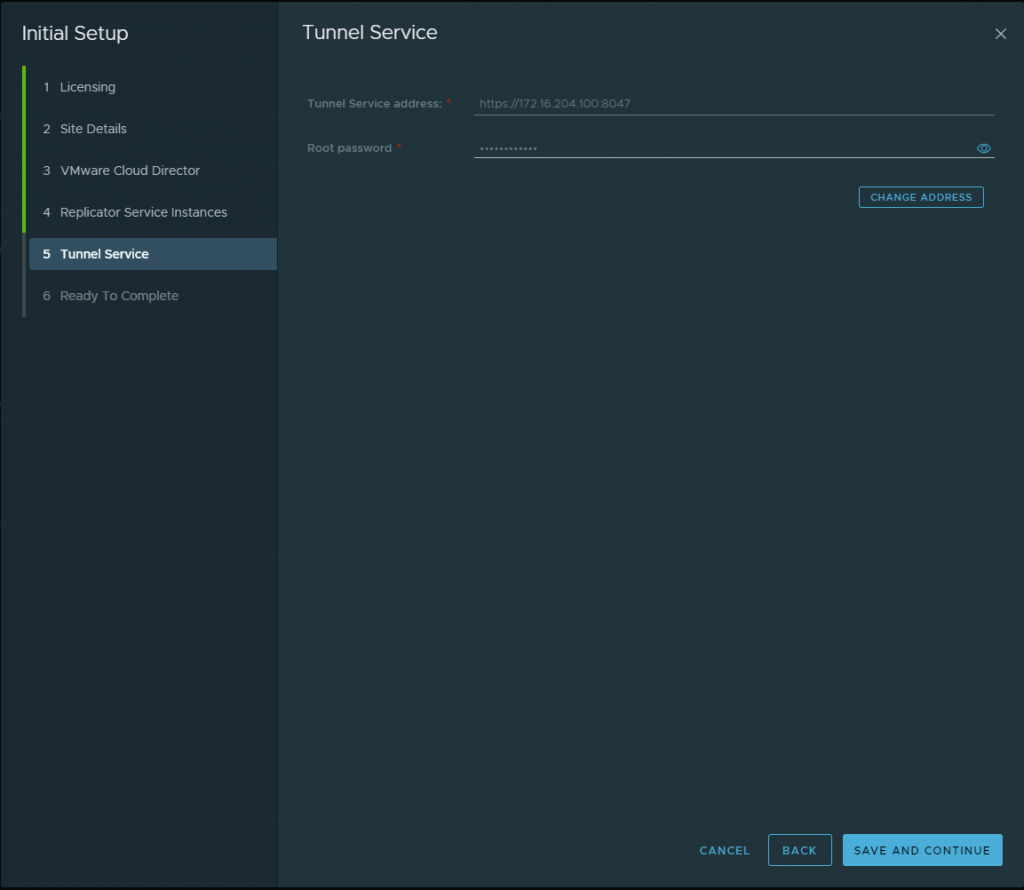
Once you have added the first VCD, then you will be asked for the next few steps. Here we will add the look up service which is the vCenter Server lookup service along with the Replicator 1 which for my setup i did a combined appliance so the IP is the same as my deployment of VCDA but my port will be different.
Then I created a basic password for this lab simulation. Use a secure password!! 🙂
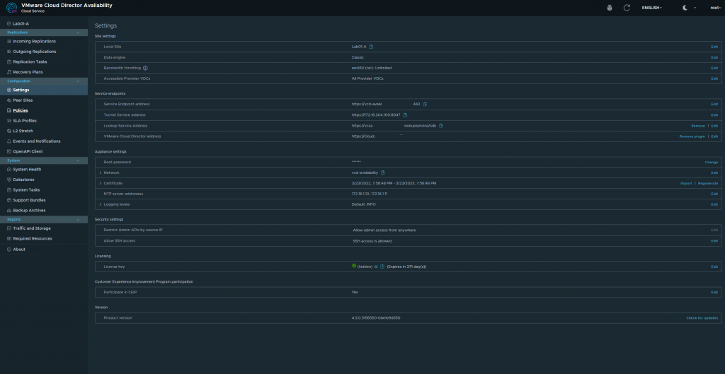
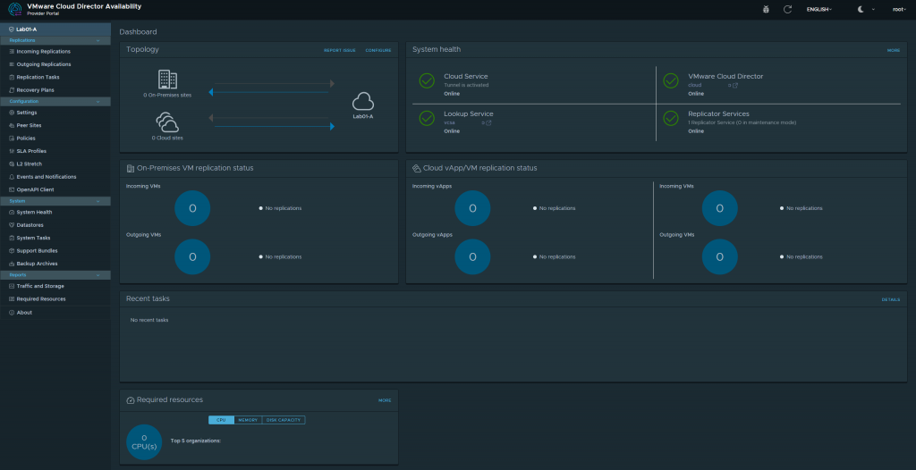
Once All is completed you shall see a dashboard like this below. We have successfully deployed VMware Cloud Director Availability! Next blog post we will get into the nitty gritty of the the migration and RPOs, and SLAs as we explore this new service which is a addon to VMware Cloud Director!