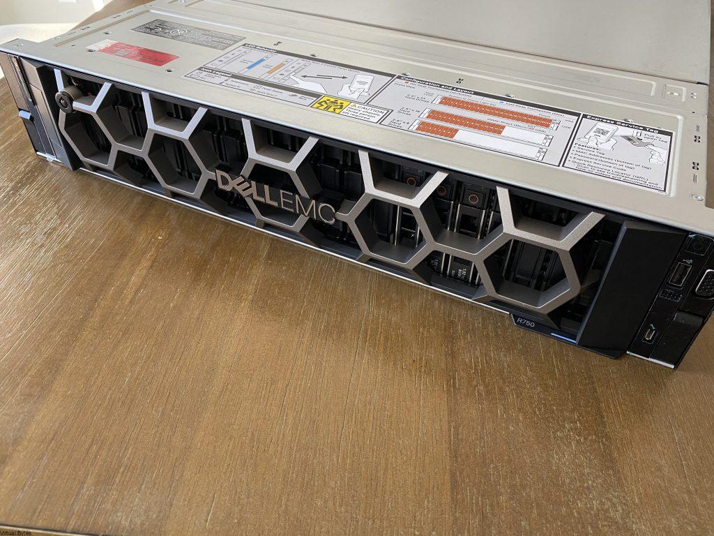
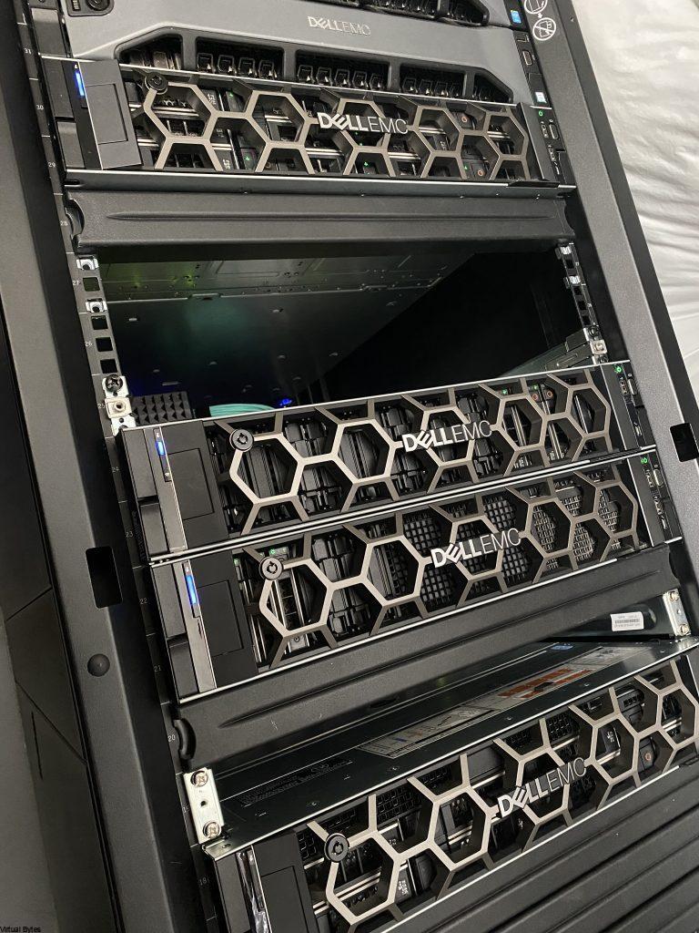
I have gotten my hands on a DellEMC PowerEdge R750. I have been grateful to collaborate with Express Computer Systems to get access to try out and create an awesome review of this hardware. This enterprise rack mount server is a powerful workhorse being powered by the 3rd Generation Intel Xeon Scalable Processors, is a dual socket/2U rack mount server. Of course, I have racked and installed it in my Home Lab 😊. During the initial unboxing, I was amazed on how this server is built from DellEMC, I mean all DellEMC Servers are built to be tough and reliable and a cool feature to see within Dell line up of servers is Water Cooling!! Yes, the DellEMC PowerEdge R750 support an optional Direct Liquid Cooling for keeping up with the increasing power and thermal workloads.
Need Enterprise Hardware? Contact Parker at Express Computer Systems
- Parker Ware – 949-553-6445
- [email protected] or [email protected]
Now, lets get into the deep dive of the DellEMC PowerEdge R750!
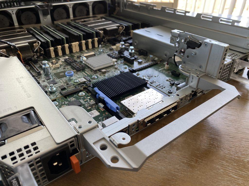
When I first opened the top cover of the chassis, I was amazed. The modular architecture that DellEMC is implementing into their new 15th Generation Servers. PCIe Risers are now much more modular than before, the tool less design – allows the riser card to be removed and install your choice of PCIe card and install it back into the server without any tools.
Specifications
- 2x Intel® Xeon Gold 6342 2.80GHz 24 Core
- 4x Dell 2.5” U.3 1.92TB PCIe Gen4 NVMe SSD
- 2x Dell PERC H755n NVMe RAID Controllers
- 8x Hynix 128GB DDR4 PC4-3200AA DIMMs
- 2x Dell 1400W Hot swap EPP PSU
- 1x Dell/Intel E810 Quad Port 10/25
Now, we will start breaking down the review and we will get into all aspects of the server.
Processors
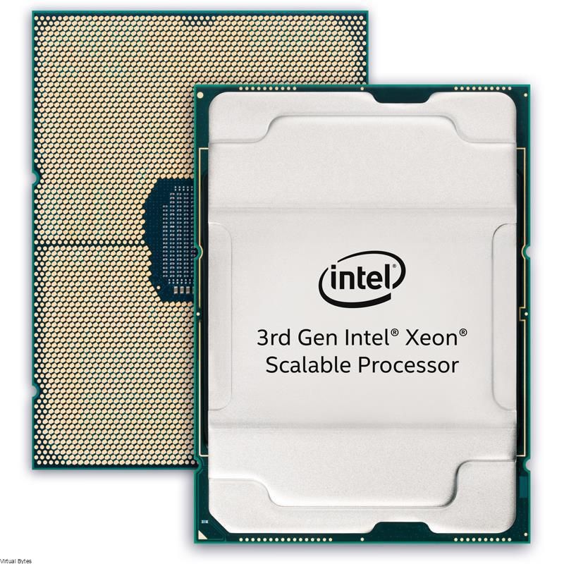
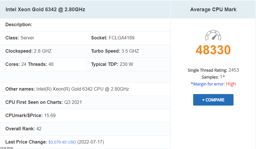
Intel® Xeon® Gold 6342 Processor (36M Cache- 2.80 GHz)
The Processors installed within the DellEMC PowerEdge R750XD, consist of 2 Intel® Xeon® Gold 6342 Processor (36M Cache- 2.80 GHz). These CPUs are very efficient power consumption for the core/watt ratio. We will get in more depth on the Power Usage in the Power / Efficiency section of the blog. Below are the Specifications from Intel’s Website, there are more features these CPUs offer, if interested check Intel’s website – here.
- Status Launched – Launch Date Q2’21
- Lithography 10 nm
- Total Cores 24
- Total Threads 48
- Max Turbo Frequency 3.50GHz
- Processor Base Frequecny 2.80GHz
- Cache 36MB
- Intel® UPI Speed 11.2GT/s
- Max # of UPS Links 3
- TDP – 230W
- Max Memory Size – 6TB
- Memory Types DDR4-3200
- Maximum Memory Speed – 3200MHz
- Max # of Memory Channels 8
- ECC Memory Supported – Yes
- Intel® Optane™ Persistent Memory Supported – Yes
- Sockets Supported – FCLGA4189
- TCASE 81°C
- Intel® Speed Select Technology – Core Power – Yes
- Intel® Speed Select Technology – Turbo Frequency – Yes
- Intel® Deep Learning Boost (Intel® DL Boost) – Yes
- Intel® Speed Select Technology – Base Frequency – Yes
- Intel® Resource Director Technology (Intel® RDT) – Yes
- Intel® Speed Shift Technology – Yes
- Intel® Turbo Boost Technology ‡ 2
- Intel® Hyper-Threading Technology ‡ + Yes
- Intel® Transactional Synchronization Extensions – Yes
- Intel® 64 ‡ – Yes
- Instruction Set Extensions – Intel® SSE4.2 | Intel® AVX | Intel® AVX2 | Intel® AVX-512
CPU Benchmarks – pulled from CPUBenchmark.net
CPU Average Results
- Integer Math
- Floating Point Math
- Find Prime Numbers
- Random String Sorting
- Data Encryption
- Data Compression
- Physics
- Extended Instructions
- Single Thread
- 193,556 MOps/Sec
- 111,134 MOps/Sec
- 233 Million Primes/Sec
- 87 Thousand Strings/Sec
- 37,043 MBytes/Sec
- 666.5 MBytes/Sec
- 3,820 Frames/Sec
- 52,433 Million Matrices/Sec
- 2,453 MOps/Sec
Memory Features
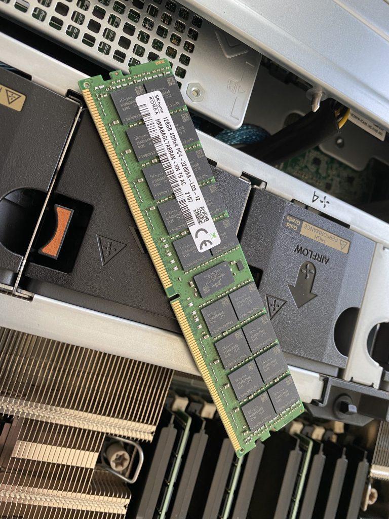
The memory, that is installed is SK Hynix 128GB DDR4 PC4-3200AA DIMM, total of 8 DIMMS. I have attached below a table of the memory specifications.
| Capacity | 128GB |
|---|---|
| Speed | DDR4 3200 (PC4 25600) |
| CAS Latency | 13 |
| Voltage | 1.20 Volts |
| Load Reduced | Load Reduced |
| Rank | 4Rx4 |
Storage
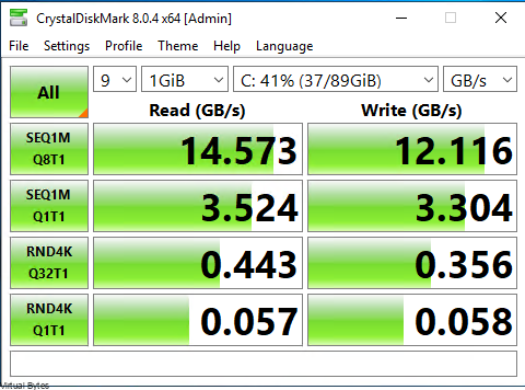
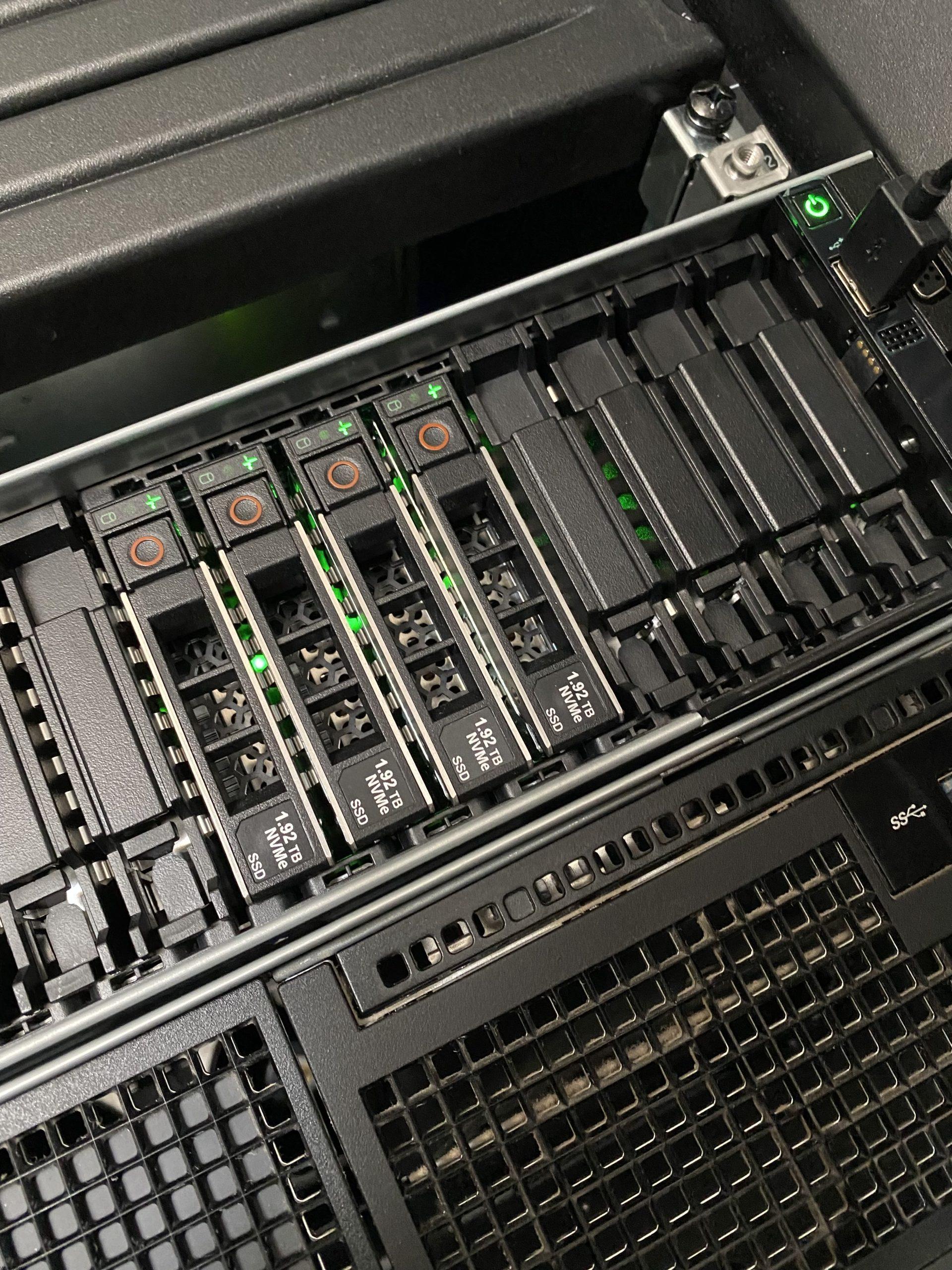
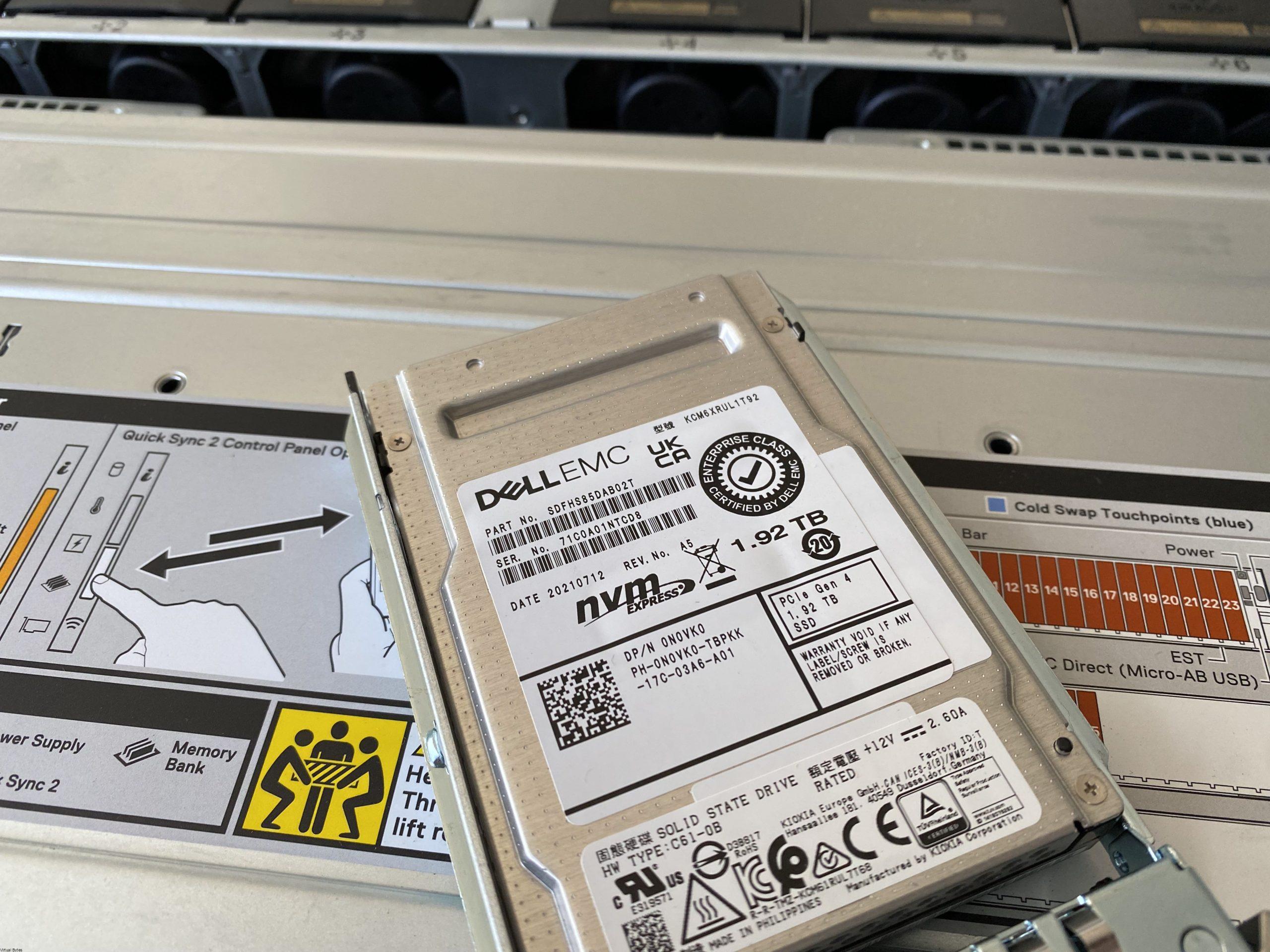
The server has 4 Dell 2.5” U.3 1.92TB PCIe Gen4 NVMe SSD. These NVMe PCIe disks have shown outstanding performance runs. I have compiled some benchmark tests with Crystal Disk Mark, below are few pictures I have taken of the Disks. The Controller that is backing these NVMe U.3 Gen4 SSDs are two PERC H755N Front NVMe.
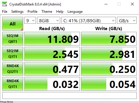
Crystal Disk Mark – Benchmark Tests.
The speeds that are shown below are tested on a virtual machine on VMware ESXi 7.03f with specifications 6vCPUs, 16GB Memory, 90GB VMDK Disk.
I was shocked, when I saw these results of a single server being able to offer these kind of speeds. I cant imagine having a RDMA setup with a vSAN Cluster with 4 of these Dell PowerEdge R750 servers. RDMA = Remote Direct Memory Access
Test on the left – 9 x 1GB Temp Files
Test on the right -9 x 8GB Temp Files
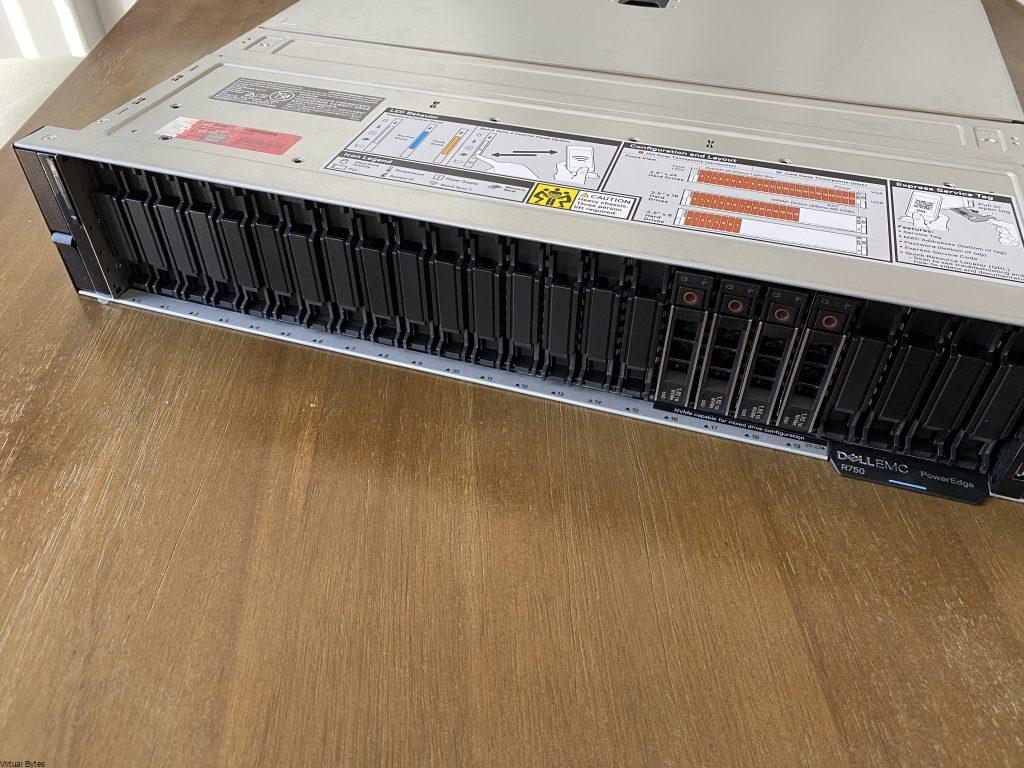
There are few configurations of the DellEMC PowerEdge R750 Series –
- Front bays:
- Up to 12 x 3.5-inch SAS/SATA (HDD/SSD) max 192 TB
- Up to 8 x 2.5-inch NVMe (SSD) max 122.88 TB
- Up to 16 x 2.5-inch SAS/SATA/NVMe (HDD/SSD) max 245.76 TB
- Up to 24 x 2.5-inch SAS/SATA/NVMe (HDD/SSD) max 368.84 TB
- Rear bays:
- Up to 2 x 2.5-inch SAS/SATA/NVMe (HDD/SSD) max 30.72 TB
- Up to 4 x 2.5-inch SAS/SATA/NVMe (HDD/SSD) max 61.44 TB
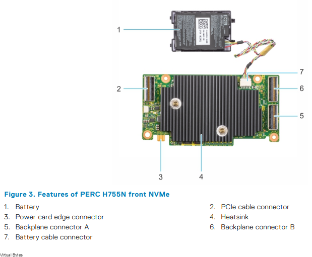
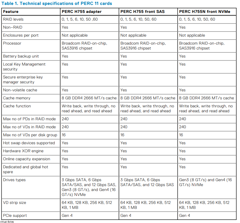
PERC H755N Front NVMe
If you would like to read up more on the Storage Controller, here is the website to DellEMC’s website.
Power
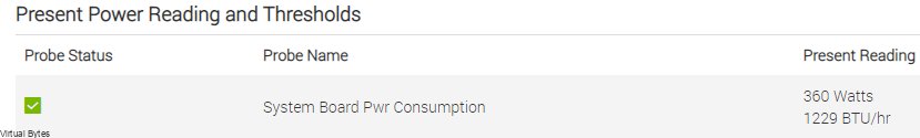
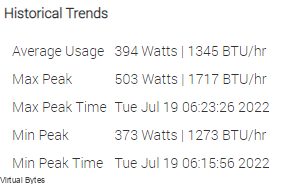
I was shocked on the power consumption, at peak I have seen 503 watts consumed, where at idle workloads the server sits around 360-390 watts with two beefy Intel Xeon Scalable CPUs and 1TB of Memory and 4 NVMe SSDs.
Below is the current power reading as the server is operational and there is workload running on it.
I have pulled a snippet of the Historical Trends from iDRAC. As you can see the power usage for the performance per watt is a great ROI on any investment where datacenters need consolidated designs where power and space are limitations.
This DellEMC PowerEdge R750 that I have up and running has two 1400watt power supplies. I have both of these connected n two seperate PDUs with Eaton UPS Systems.
Detailed Info about the Power Supplies (DellEMC)
| Power Supply Units(PSU) portfolio | Dell’s PSU portfolio includes intelligent features such as dynamically optimizing efficiency while maintaining availability and redundancy. Find additional information in the Power supply units section. |
| Industry Compliance | Dell’s servers are compliant with all relevant industry certifications and guidelines, including 80 PLUS, Climate Savers, and ENERGY STAR |
| Power monitoring accuracy | PSU power monitoring improvements include: ● Dell’s power monitoring accuracy is currently 1%, whereas the industry standard is 5% ● More accurate reporting of power ● Better performance under a power cap |
| Power capping | Use Dell’s systems management to set the power cap limit for your systems to limit the output of a PSU and reduce system power consumption. |
| Systems Management | iDRAC Enterprise provides server- level management that monitors, reports, and controls power consumption at the processor, memory, and system level. Dell OpenManage Power Center delivers group power management at the rack, row, and data center level for servers, power distribution units, and uninterruptible power supplies. |
| Rack infrastructure | Dell offers some of the industry’s highest- efficiency power infrastructure solutions, including: ● Power distribution units (PDUs) ● Uninterruptible power supplies (UPSs) ● Energy Smart containment rack enclosures |
Cooling & Acoustics
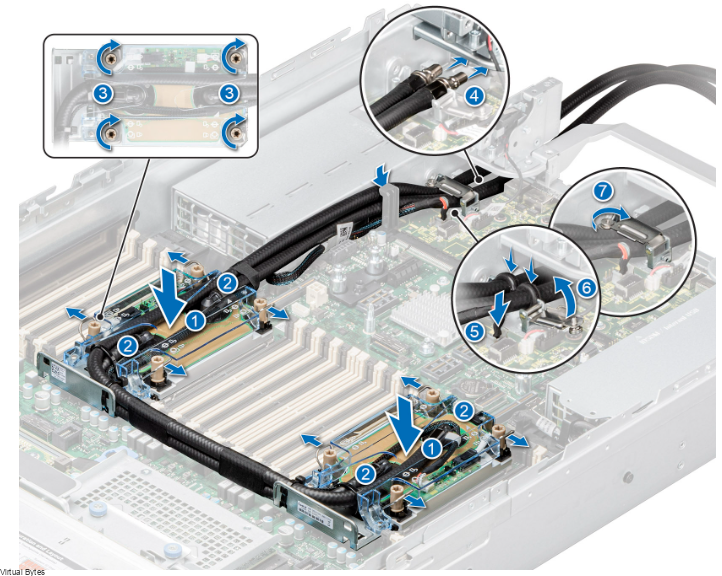
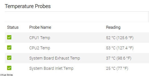
I have pulled Temperature statistics, as of writing this review. The CPUs are staying very cool, which the new “T” shape cooler design spreads the heat out evenly and which allows the CPUs to cool down quicker than the older traditional tower heat sinks where the heat had to rise up through the copper pipes.
Direct Liquid Cooling – New 15G PowerEdge platforms will offer CPUs with higher power than ever before. Dell is introducing new Direct Liquid Cooling (DLC) solutions to effectively manage these growing thermal challenges. Dell DLC solutions cool the CPU with warm liquid which has much greater (~4x) heat capacity versus air. Thus, DLC is a higher performance cooling solution for managing the CPU temperature while also enabling higher performance and better reliability more info at (DellEMC)
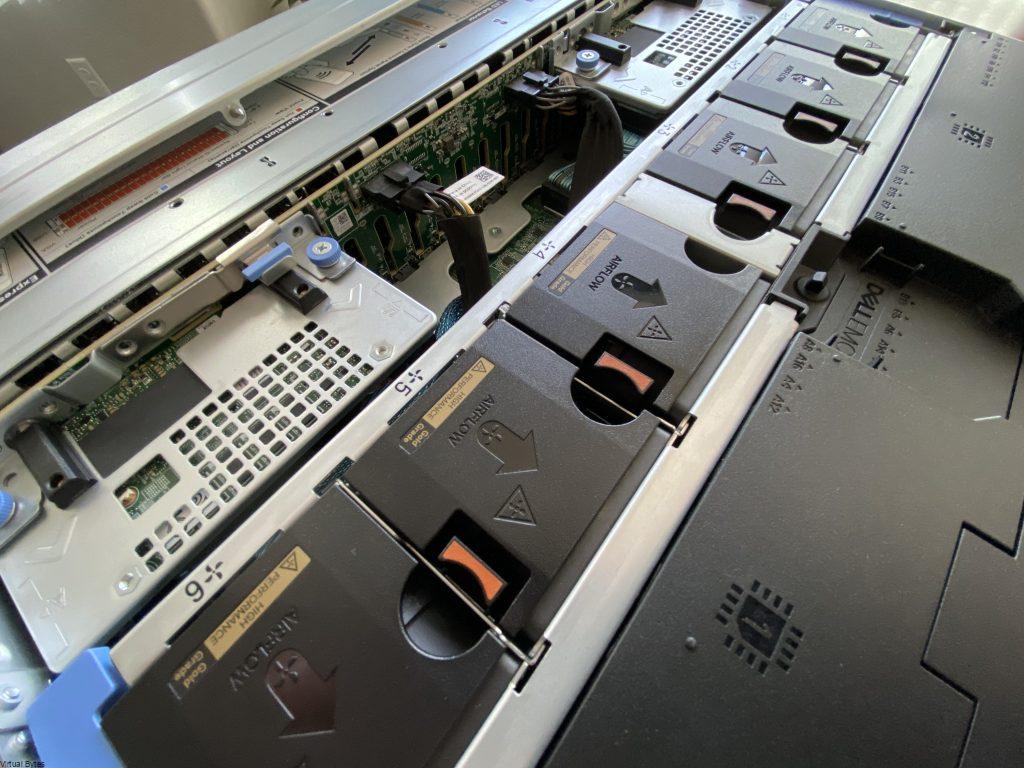
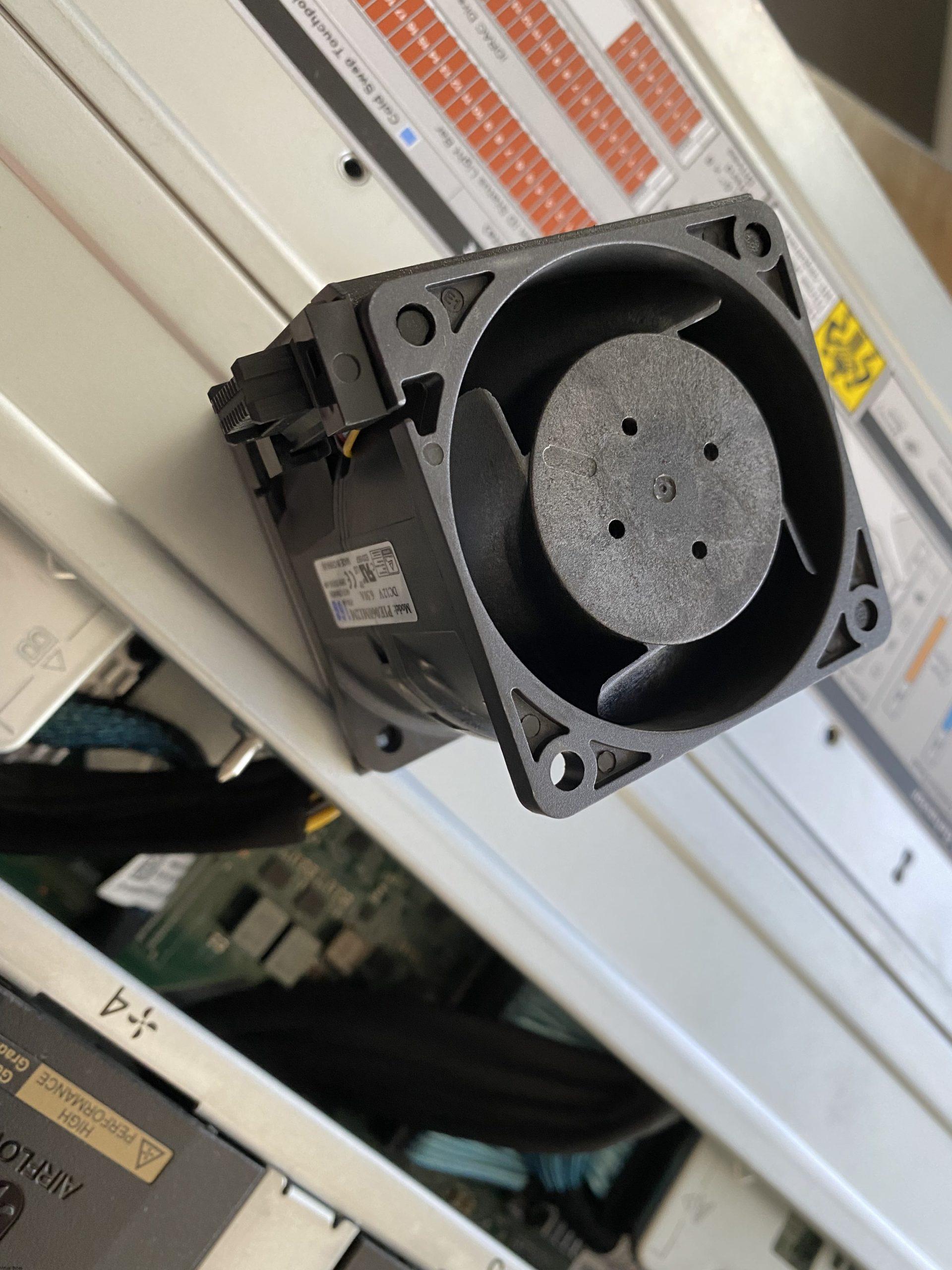
Thermal Statistics & Fans
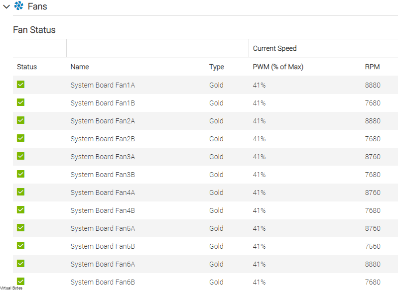
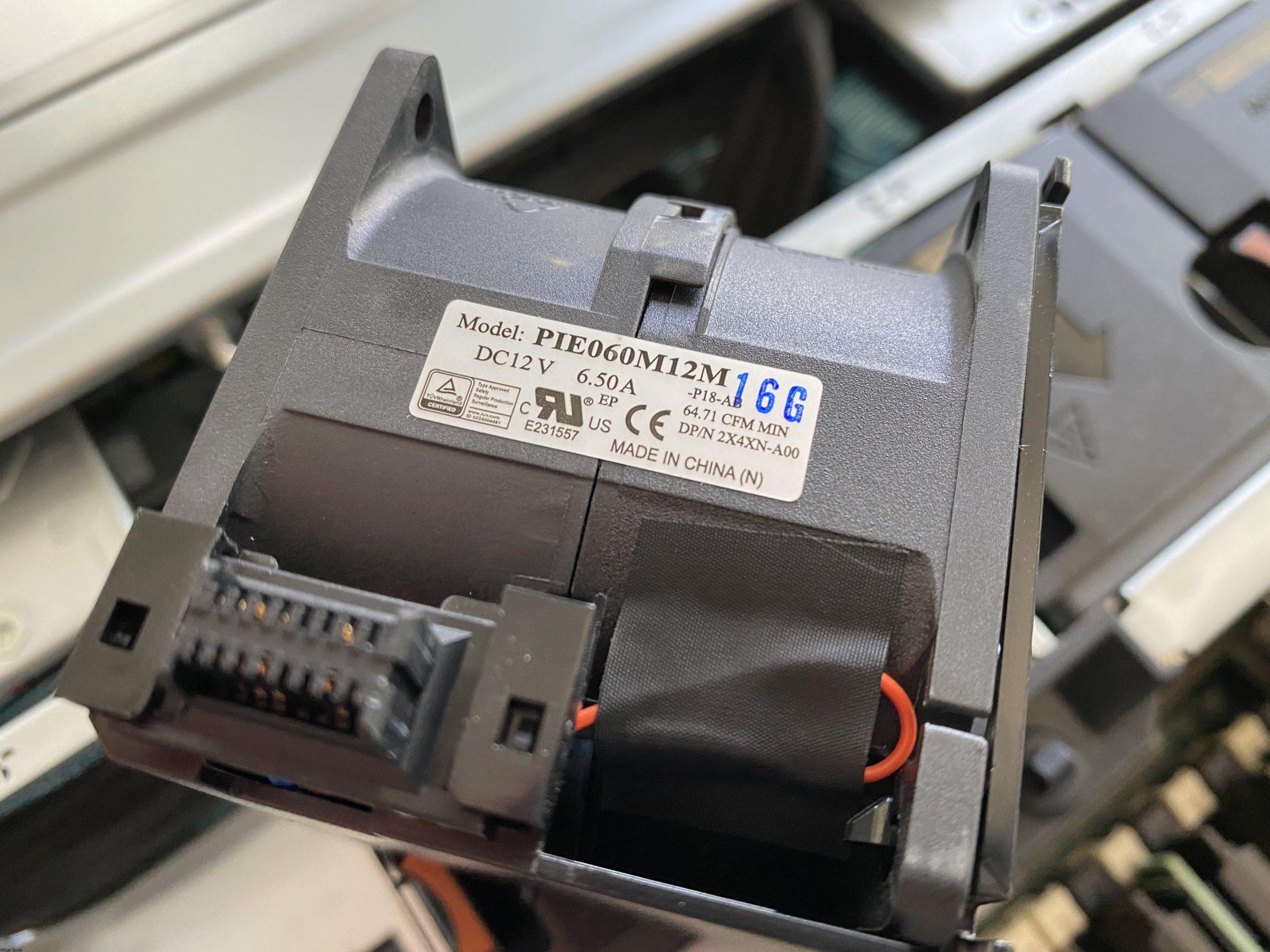
High-performance fan (Gold grade) fans – Power Specifications 6.50A 12 Volts.
Disclaimer! Mixing of STD, HPR SLVR, or HPR GOLD fan is not supported.
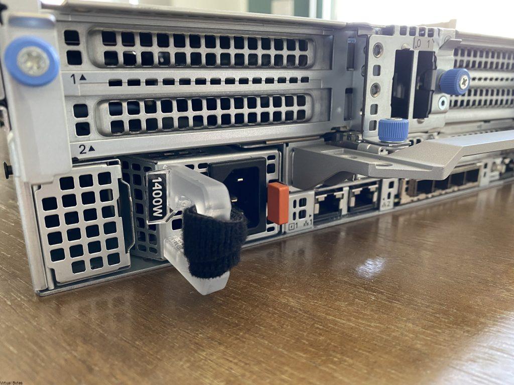
Front & Rear I/O
In the front, the Dell PowerEdge R750 offers:
- 1x USB
- 1x VGA
- 1x Maintaince port
- 1x Power Button
- 1x iDRAC Locator & iDRAC Sync
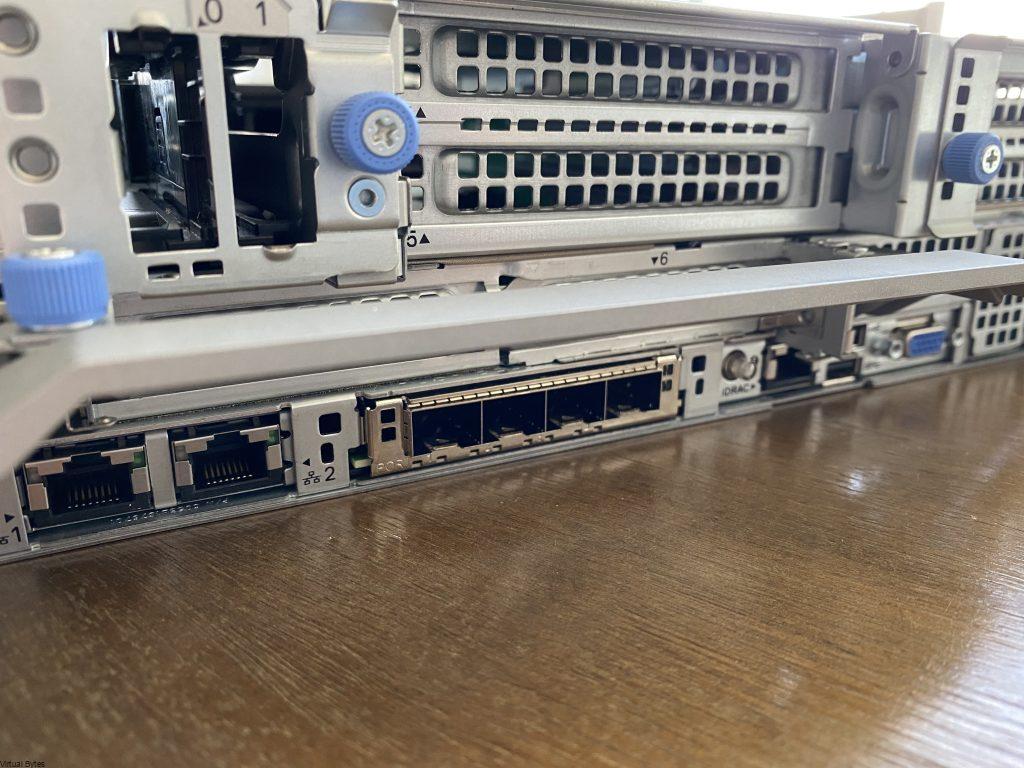
In the rear, the Dell PowerEdge R750 offers:
- 2x DellEMC Boss Card Slots
- 2x 1Gb LOM
- 6x Large PCIe Slots
- 4x 10/25Gb NDC
- 1x iDRAC
- 2x USB 3.0
- 1x VGA
The Riser topology that DellEMC has started using within the Dell Line up of 15Generation servers is really neat, I like how easy and quick it is to take out a PCIe riser. No Tools are needed! Within minutes I was able to take apart the server and have all the risers out, there is two cables that are connected to Riser 1 which is the Dell Boss NVMe/SSD card which is labeled “0,1” once you disconnect those two cables it’s a breeze!
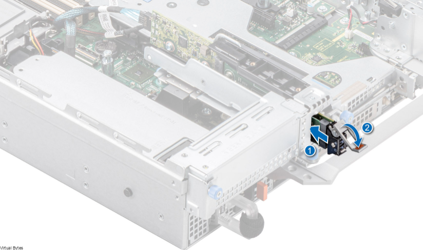
Dell BOSS S2 module – They are now hot swappable! Before when you needed to swap out a boss card, you had to migrate off your workloads, and shut down the server and pull the top cover, then pull out the PCIe Dell Boss card from the riser and unscrew the NVMe / SATA SSD from it. Which that would impact workloads to business continuity. Now, with Dell 15th Gen Dell PowerEdge R750. You can HOT SWAP! This will improve efficiency of replacing failed boot disk and bringing workloads back up in matter of minutes rather than hours!
References to Websites – in direct links in each section with any content from DellEMC / VMware etc.